.png)
Hi all,
I am sorry to repost this, but in my first post I did not post enough detail on what I am doing so I wanted to start over.
I am making a chess playing robot which is similar to Mahtatuur's project and I was talking to him and he advised that I post about the project here.
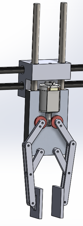
I will be using 2 stepper motors for movement in the XY direction and 2 D.C. motors, one to move in the Z axis and the last one to open and close a gripper.
At the moment I am building the physical project and have been searching online for similar programmes which I could use.
The gripper will move up/down by a DC motor and gear set turning the bar on the right. The bottom part of the gripper wil be tapped so that it will move up/down on the threaded bar when it rotates.
I am using 64 magnetic reed switches under each square of the board to tell when a piece has been moved. This is the schematic for the circuit I will use. 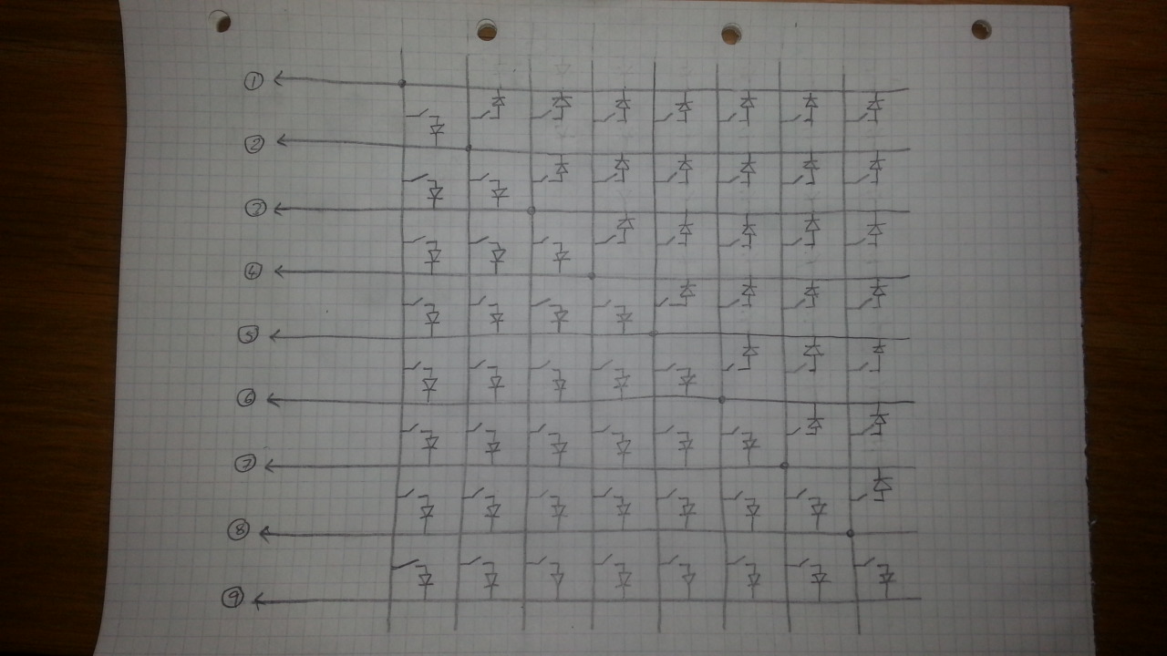
At the moment the problem I could do with some help with is writing or finding a suitable program which will allow me to sense the state of the switches on my Arduino UNO??
Thanks in advance,
Paddy :)
Hello and Welcome Paddy
Hello and Welcome Paddy !
Looks like you have a very good, well organized, nicely designed start ! Hope to see more as you progress.
Regarding your question about the program I think MRL would serve you well. It already has (a couple) Chess game engines in it. I think they both have online displays too (one is in Swing and the other is Web if I remember correctly). MRL (myrobotlab) can orchestrate all the event and control messaging that you will need.
It will take a little work, for example steppers in MRL are implemented but I think its an area we would like improvement over. I assume you'll have limit switches of some sort for the 2 DC motors - which should be pretty straightforward to implement in MRL.
I'd recommend asking input from Mehtaatur, he has developed a really great system.
Also visit the ChessGame service page - http://myrobotlab.org/service/chessgame
Additionally, you may get other ideas from the current list of Services to combine with your own system - http://myrobotlab.org/matrix.php
This reminds me Mehtaatur and
This reminds me Mehtaatur and I had some ideas about making a game manager and several other improvements. I believe he and I got distracted. I would be curious if he remembered what the enhancements were and if they are still of interest.
Hehe Grog, yes I remember we
Hehe Grog, yes I remember we spoke about having a game manager and other improvements. I dont recollect the specifics but I guess it was about implementing chess gameplay via internet using websockets and having a better chess engine.
At that time we still had lots of finishing to be done on the hardware so got little distracted.
One of my team members recently made a servlet for testing online game play. Hopefully in few days we should have positive outcome
Will update you.
Welcome PaddyMcd
Hey,
Amazing start paddy, you've got the hardware designing all sorted and with MRL the whole project would be very simple to implement.
I have few suggetions to make:
-Use servo for closing/opening the gripper as it gives feedback and constant torque.
-U might want to consider using an arduino Mega for this project as Uno has max 20 pins and you require might require more depending on your stepper motor driver.
-as Greg suggested you should also consider using the limit/homing switches for the stepper motors.
I also have a doubt regarding the wiring diagram shown, I do not understand why the diagonal half switches are connected to upper column.
For programming the stepper motors, you could use MRL in two ways:
1)Use MRL's Arduino firmware and program the whole thing using Python.
2)Use MRL's serial service to communicate with Arduino (ie: passing the coordinate values from the chess engine to arduino)
*Greg, please advise which method is best for this application.
For reading the switch state, you need to use a double for loop (ie: activating each column and checking respective rows for change in state).
Once you decide on how and what all service of MRL you plan to use, we could test few scripts.
All the best, excited to see future development of this project :)
Hi Grog, I did have a good
Hi Grog,
I did have a good look at Mehtatuur's blog posts and got some good ideas from there even already. I have also had a few words with him and he advised me to post here.
Yes for the gripper I am going to include a limit switch to spot the gripper closing, but I hadnt though of a limit switch for the Z axis movement but it does seem like a good idea.
Any sort of contribution would be greatly appreciated. I am doing the project for my Final Year Project in college and at the moment I am trying to focus on getting the project working and if possible I would then like to come back to it and make further improvements.
- I had thought of using a servo motor but when I was coming up with the design of the project I decided to go for the DC motor and worm wheel mainly for aesthetic reasons and I actually have the parts for the gripper half made already. Would the servo be a much better choice?
- For the stepper motors I am using two EasyDriver that can be seen here https://www.sparkfun.com/products/retired/10267 From what I have seen, the UNO should be able to drive these motors??
I was trying to do some research on charlieplexing to wire up the switches because it would mean I would not have to order any extra chips, at least that was my understanding of it. Would the imade you posted yesterday of your wiring be more suitable?
Yesterday I updated my Arduino IDE to 1.6.1 and since then I havent been able to upload any sketches to my board. I searched online and many people advised updating my drivers but they are all fully up to date.
I suggest the arduino Mega
I suggest the arduino Mega because:
the 8x8 array of sensors will need 16 wires + 2*(3 wires for 1 stepper motor) + 2*(2 wired for 1 dc motor) = 26 wires
additionally you might want to add a buzzer or button or anything else which will need more IO.
But since bare minimum IO's needed is 26 you will need to use an Mega or some other Micro with more IO's. you coud use the UNO for testing individual blocks.
I use this library for controlling stepper motors (http://www.airspayce.com/mikem/arduino/AccelStepper/index.html) do check it out, it supports acceleration and simultaneously running two motors together.
Both MRL and Arduino support this motor library.
I was surfing the net to find out alternatives for Reed Switches.
checkout: http://www.thehypertext.com/tag/mechanical-turks-ghost/
Ross Goodwin has made a sensing board using Hall effect sensors, they are more accurate than reed so I advice you use hall sensors.
I for got to add, I purchased
I for got to add, I purchased a Mux shield which gives 64 aditional pins. I bought this when I thought I would have to wire up each switch individually to a pin. This together with the arduino UNO should be more than enough? http://macetech.com/store/index.php?main_page=product_info&products_id=…
I hope I will recieve my motor drivers by the end of this week so then I will be able to start doing some tests with different programs. For now I am just going to read through the given examples to try and understand them better.
I am getting a PCB made on Thursday for the sensors below my board. If I use hall effect sensors would the schematic be similar but with all pins connected at the ground pin and this go to the ground on my arduino?
I am going to make a small 3x3 matrix to test the reed switches and if they do not work I will then use the hall effect sensors.
I think the Sheild will take
I think the Sheild will take care of the additional IO since it uses I2C.
For the hall sensors, the schematics WILL be the same, you will just need to give a common ground to all sensors with the arduino as the hall sensor is a 3 pin sensor.
Making a 3x3 matrix of reed switches will be a good way to test the accuracy, waiting to know how well it works out.
All the best with the PCB making, do post an updat once you are done :)
Ciao!
From MRL's perspective - the
From MRL's perspective - the I2C and IO board makes things a little more complicated than just having a Mega..
Mehtaatur I believe needed to merge MRLComm.ino and his own firmware into the arduino, which you probably will need to do too... not really a big deal
Possibly with a Mega you won't need to do that.. but no guaratee ..
Also a possiblity to grow .. currently MRLComm.ino does not do I2C relaying, but I have meant to do this.
To help with the merge we have meant to turn the sketch into a library - we had issues in our previous attempt, but I have some ideas on how we might resolve them.
When I started using MRL
When I started using MRL initially I didnot have much Idea about the MRLComm.ino
I also thought of merging my firmware with MRLcomm but wasnt so good at coding back then.
So instead I wrote my firmware on Arduino in a way that it communicates back and forth with MRL using Serial Communication. (Thanks to Grog for fixing all bugs and broging Serial services in MRL )
)
@paddy, you could also try this method, Let the UNO do the muxing and stepper control and MRL take care of chess engine programming, let both the platforms exchange data over serial cause both Arduino and MRL have very strong and reliable Serial Interface.
@Grog, instead having a library, wouldnt it be easier if we could implement a Serial protocol for the arduino to communicate with MRL? That way the Arduino can work independently and communicate with MRL only when required, since Serial communication on ardunio is using interrupts, MRL can be the master device and cause and interrupt anytime.
Not sure what you mean
Not sure what you mean mehtaatur.
As a library - MRLComm.ino could be used in any Arduino sketch - you could get data from and send data too MRL using the library.
You'd initialize it with a serial object - since Serial communication is a requirement for MRL...
this would be sketch example:
I tested out the 3x3 matrix
I tested out the 3x3 matrix using the reed switches and LED's to tell when they were turned on or off and even through the board this seems to be workign reliably. For some reason I cannot upload a picture now but it is working.
At the moment @mehtatuur I also don't have much knowledge about the MRLComm.ino.
I hope I am following correctly but that is what I had in mind, MRL would control the game of chess
- MRL would send its move to the arduino as co-ordinates and the arduino will control the motors to move the piece.
- I would then make my move, the magnetic reed switches will tell which piece has been moved and to where and that would be sent to MRL which will then respond with it's own move?
I am getting my PCB cut out
I am getting my PCB cut out tomorrow for the switch matrix for under the board and am hoping to have it soldered up by the weekend.
In regards to the co-ordinates I have been doing some research on G code and trying to use G code with the arduino. @Mehtaatur you mentioned in a previous comment that I could use the MRL's serial service to pass coordinate values from the chess engine to the arduino.
Im excited to know how the
Im excited to know how the PCB turns out ofter soldering, do send us pics :)
About G-Code, to make the motors move using Gcode, you will have to use an Gcode firmware like GRBL, etc...
But the problem with this is that then you will not be able to read values from reed switches easily, to get both the functionality, you will have to modify the firmware and also write a script accordingly [ thats what i understand], so i choose not to do this.
In my case, i wrote a script which takes the move coordinates ex: "a2a4", then parses this string to make motor movements. Motors are moved to the respective coordinates using Accel Stepper.
@Grog, please provide your feedback on this method, can it be improved?
I don't think you need G-Code
I don't think you need G-Code firmware ... The EasyDrivers make it easy ... 1 step and 1 direction pin ..
Do you have a "reset" switch on the X & Y axis?
Theoretically.. If we work on Steppers together - we could get Steppers to run directly from MRL & MRLComm.ino. That is, if we improve MRL's Stepper service & MRLComm.ino - you won't need any "custom" firmware at all. Python & the chessboard will control it all.
The PCB's came out very
The PCB's came out very well. I had to make two seperate ones to fit underneath the chess board but they seem to be working well. I am meeting up with a friend on Tuesday to try and write a script to read the state of all the switches.
@Mehtaatur have you still got that scipt by any chance?
@Grog, do you think it would take long to get to the stage where we can run the steppers straight from MRL?
Very nice Paddymcd ! Looks
Very nice Paddymcd ! Looks great :)
No - would not take long - much of it is already done - what is needed is some "actual" hardware and coordinated effort. Even if the board is not finished we could start on finishing the stepper control.
You and I would need to work together - I would need to see your system in a pictures with detail description of what is hooked up. You would need to tell me the goal.
Change your Avatar you are not a scared Chipmunk anymore ! :D
Ok sounds good Grog, what I
Ok sounds good Grog, what I have gotten now is two stepper motors driven with two easydriver stepper mortor drivers. I wired these up just to test the board and motors were working, I will have to add longer wires between them.
I will also be using the Mux shield I mentioned above as i have more wires than the UNO has pins. Will it make a difference if I connect the stepper to the shield or the Arduino itself??
Avatar changed as well :D
Great. I found this helpful
Great.
I found this helpful reference from SparkFun - http://bildr.org/2011/06/easydriver/
the mux shield looks mostly like a pass through - although I would expect some of the pins are dedicated for muxing - as long as those pins are avoided I think plugging in the easyboards should be fine.
The easy board looks very "easy" - nice .. only direction and step - lets just do regular step - I don't know the details about all the fraction/micro-step stuff - but first round we'll keep it simple ..
Working on this now...
Hey Guys, @paddy the PCB
Hey Guys,
@paddy the PCB looks neat... is this just a trial 4x4 PCB?
A very basic script for testing 4x4 would be:
WOOHOOO ! More stuff to
WOOHOOO !
More stuff to implement - I wanted to implement I2C relay in MRLComm.ino ... this gives me a reason to do so !
No this is the full board, I
No this is the full board, I just cropped the photo so it would fit in better. This is the full one, I must attach jumper cables between the rows to connect.
I will connect up 4x4 of this just to test it to see it is working.
In terms of the physical making of the model I am just waiting on the legs I will be almost finished. I have holders for all of my motors and pulleys. I still have to wire these up when they are in position.
I will put up another photo when the legs arrive and I have the motors connected up.
A worry I'm after having is that the slides dont run very smoothly in the extrusions because they are fairly tight. I think having the motors running quite slowly for extra torque would be the best idea, would ye agree? When giving up my project I can say how I would change this in the future to give more speed.
Ahoy Paddymcd :) I'm working
Ahoy Paddymcd :)
I'm working on MRL's Stepper & firmware code - I'd like us to work together to make it satisfactory.
First - can you check and make sure this code works for your steppers ?
http://bildr.org/2011/06/easydriver/
Please experiment with the speed values - and see how it affects the motors .. what would be a good default speed ? I plan to make the speed dynamically updatable, so that it does not require a reload of firmware to change speed - it would become just another command MRLComm would take.
Another thing I would like to know, and maybe Mehtaatur would have an opinion too, but I'm wondering if Absolute or Relative positioning is better for a stepper ?
Let me describe:
Initially all steppers have no reference at all - you need a start position - which is just when the program begins the current position is 0. Or you need to move the stepper until you get to a switch which then you "reset" the position - this initial position becomes 0.
What I am interested is on subsequent moves .. do you want steps counted relative to your last position (relative) - or do you want steps counted from your first reset (absolute) ?
Now an example :
relative
stepper.move(30)
stepper.move(40)
stepper.move(-15)
absolute
stepper.moveTo(30)
stepper.moveTo(70)
stepper.moveTo(55)
In both of the cases, the final destination of the stepper is 55. I think I just answered my own question though - I think it would be good to have both :)
And maybe with the name of the methods its clear as to what it means ... move is a move relative to the last move.. moveTo is absolute positioning..
Ok, moving on - if you could provide some feedback as to what results you get with experimenting with the easydriver code @bildr ..
@Mehtaatur - is your stepper firmware similar to the easy driver? Do you utilize a stepper hardware driver similar to easy driver or does your interface require you drive each stepper wire? I intend to support as many drivers and steppers as possible. The Arduino itself could drive a stepper directly with appropriate logic, as long as it could give the require current. What I mean is the Arduino + a handful of transistors could be hooked up directly to a stepper - but this requires the logic to change to the appropriate pulse sequence the stepper requires. Could you please provide details to your driver? Thanks !
I just tested that code on my
I just tested that code on my steppers Grog and it seems to be working perfectly. In the code it says the speed can be changed from .1 - 1. I think .5 would be the most suitable as the strength it at its highest and still provides a good speed.
One of the main things I am not sure about is, how will we communicate the moves made from the chess engine as co-ordinates to the arduino?
Hey, Firstly, Im sorry for
Hey,
Firstly, Im sorry for not replying promptly due to my ongoing exams.
@G, As u said above, it would be good to have both absolute and relative positioning functions. Im my scripts I have majorly used moveTo(), but for few small actions I have also used move().
My stepper functions is slightly different from easy driver. I use the 4 wire logic control using L293D IC(which does the job of the transistors u mentioned) for driving steppers using AccelStepper Library (which I guess is also being used by MRL), this library supports various drivers along with easyDriver.
Easy Driver uses 2 pin control and I have been using 4 wire control. the best part of this library is that I can change my hardware with minimum(3-4 lines) change in software.
@paddy, regarding your concern for sending coordinates of chessMove to Arduino its very simple. But i guess you do need to do that, because you will be parsing the move within MRL and sending stepper motor commands using moveTo(), on the ardino side MRLcomm.ino will take care of the rest.
Hi lads, I decided I am
Hi lads,
I decided I am going to make a new post for the project now that we are moving onto software completely. Ill post my update there