In this blog I hope to receive all info we need, to build a good stabile PPM or I2C Servo Decoder.
If someone else gets a better idea, please share your ideas ;-)
At this moment I've included at the InMoov NervoBoards only a I2C connection for a Arduino Uno !
In a newer design, I will include this option also for the Arduino Mega.
More info from my side will come soon.
Thanks in advance.
Regards,
Marten
Some links about PPM (Positive Position Modulation)
http://www.omegaco.demon.co.uk/mechtml/fmectech.htm
Here a old way with a HCF4017B ic:
http://myweb.tiscali.co.uk/norcimradiocontrol/Radio6.htm
http://www.st.com/web/en/catalog/sense_power/FM140/SC1850/PF63009
This week I will receive my designed PCB's:
This PCB has 9 Servo outputs and it can be used with a RC network (R1 and C1) including D1.
Or we can use a digital output pin to sent the Reset puls.
With a RC network, we only need three cables: Power, GND and Signal
With a Digital output pin, we can safe some time because we can keep the Reset puls shorter !
With my PPM Encoder (PIC based), this PPM decoder works great with both options.
A other option is to think about a Arduino based Decoder, connected via Serial, I2C or USB.
This will give some options to include the servo-speed functions.
Here a PPM Encoder from ArduPilot:
https://github.com/diydrones/ardupilot/blob/master/Tools/ArduPPM/Libraries/PPM_Encoder.h
Nevro Board PPM
I think PPM is the easiest path to go for driving the servos.
It's great that you work on the Nevro Board to decrease the number of cables needed to control the servos.If you put a 4017 on each board to drive 9 servos it would be so great. The background, hardware and software to use the 4017 from Arduino is very well described in here. http://rcarduino.blogspot.se/2012/08/arduino-serial-servos.html.
If I understand the possibilities correct, a 4017 has 10 outputs, but only 9 can be used to drive servos, since one has to be wasted. It's output will be high when no servo pulse is sent. The Arduino Uno can drive 2 PPM streams on 2 pins because it has 2 timers. So 18 servos on an Ardino Uno. Arduino Mega has 4 timers and can run 36 servos on 4 PPM streams using 4 pins. One stream for the head, and two for the arms. One for the stomach.
Some adjustments are needed to make it possible to use from MLR.
1. Check for the latest verison of the RCArduinoSerialServos library and compare it with the Servo library. They should both implement similar methods.
2. Update MRLconn ( i.e the MRL part of the software executes in the Ardino ) with new commands that use RCArduinoSerialServos.
3. Update the MRL Servo service to be able to attach servos using RCArduinoSerialServos and send the correct commands to MLRconn.
4. Build some hardware to be able to test .
Hello Mats, Thanks for your
Hello Mats,
Thanks for your reply and for the link.
For some reason, the link didn't open the correct page.
So here the same link: http://rcarduino.blogspot.se/2012/08/arduino-serial-servos.html
About the software side, I'm sure I need some help to let this work correctly.
For the hardware side, I can use my PPM_Decoder PCB.
I hope to receive them tomorrow
And yes, there are 10 outputs at the 4017 ic.
The reason why we can use 9 outputs, is because of the reset function via the RC network.
If the Reset pin is active, the 4017 pin Q0 is set to HIGH until the reset is cleared.
This Reset time is to long for a servo PWM puls lengt.
The only option that we can use the Q0 output, is that we can link the Reset function together with a Servo puls lengt.
This means that 9 servo's are controlled by the Clock-pulses and servo 10 during the Reset function.
This option is I think included by the Arduino Serial Servo Library.
Hardware
@Marten
I will order some other electronics that i need for my 3D printer, so I will also order some 4017's.
What parts/ values should be used for the other parts. I.e R1-R3, C1-C2, D1, T1 ?
I will use an Arduino Uno and a simple prototyping board to test the software changes.
PPM 4017 Decoder schematic
Hello Mats,
Here a schematic for the 4017 Decoder:
For D1 I've used a BAT83 (High Speed Shottky Diode)
R1 at this schematic isn't needed.
For the 4017 ic, make sure you order a HCF4017B from ST !
Here my partlist:
HCF4017B ic
R1 = 390K
R2 + R3 = 10K
C1 = 22nF
C2 = 100nF
C3 = ? (Buffer elco)
D1 = BAT83
T1 = BC547
Pin-out 4017 ic:

Here you can see what happens with the RC network during the complete PPM loop.
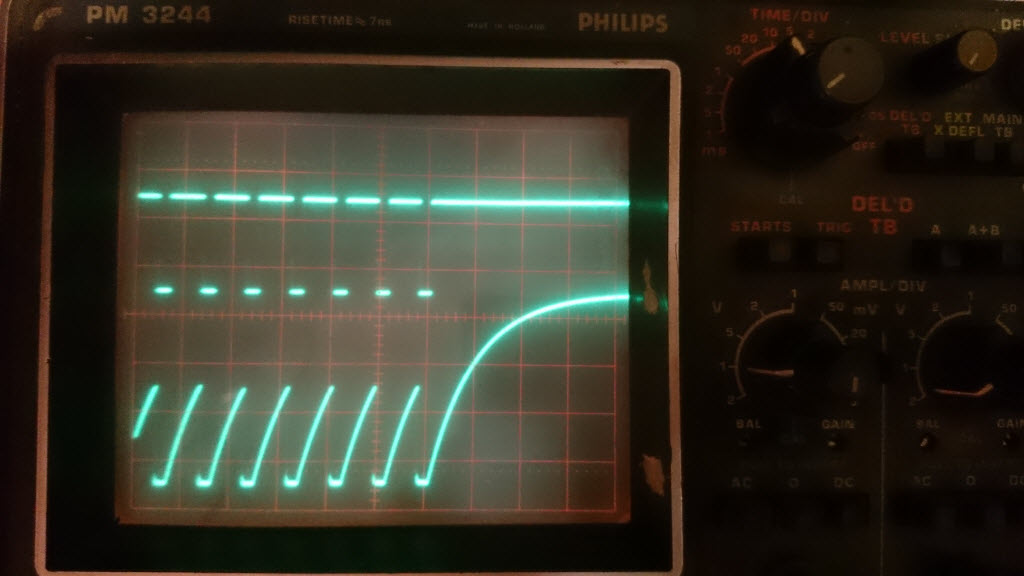
PPM is at the top and the RC + D1 network is at the bottom.
If you like to use the Arduino Serial Servo's Library, you only need a HCF4017B ic.
Power sensors
I see in many places that servos burn out. Since you are designing a new board to be used as a servvo interface, it would be nice to have it support two more things.
1. Measure the current passing to the servo. It could be used for measuring the force that the servo applies.
2. Protect the servos from burning. Perhaps a simple cicuit that triggers reset on the 4017 in case of high load.
Hi Mats, It's a good
Hi Mats,
It's a good point.
I'm not sure if this can be done with a easy circuit to keep the board small enough !
(electronics is just a part of my hobby :-) )
I'm sure MRL can do some easy things in the software.
Like a servo-speed/acceleration slider for all servo moves.
This can be used during a first test configuration and even in the main program.
I think the most servo's starting to fast when they go to the new position.
A other thing, is to think about a better mechnical way, to get more torque by less power.
And it's good to safe weights in all long pieces like the arm/hand/fingers.
If it's possible to use smaller servo's for the fingers and we can keep the same torque, it's a good upgrade.
Different way to hack the servos may help
Hi
The way servos are hacked for continous operation is cutting the endstops, and moving the potentiometer outside the shell and then use original servo control. I.e a specific pulselengt corresponds to a specific position.
When I built wheeled robots some years ago, I made a similar hack.
But I just set the potentiometer so that a 1500ms pulse would make the servo stand still. A shorter pulse would make it turn in one direction, and a longer puls on the opposite direction. If the pulse was 1600 ms the servo would turn slowly, and at 2000 ms it would run at full speed. So if the original pot is adusted this way, an additional pot could be used to externaly measure the position. The pulselength then controls the speed of the movement, not the position.
That would be an easy way to control the speed and also get a reading of the actual position, rather than hoping that the servo will reach the desired position. But it reqires that the position is read and that there is a control logic to stop the movement when the desired position is reached.
Hi Mats, Thanks for your
Hi Mats,
Thanks for your input about this.
It's possible to hack a servo as you said.
The most easie way is to use two resistors in serie and picking up the signal between the two resistors.
This is normaly around the 1500ms point.
I'm not sure if it's possible to use one Arduino to check all the positipons for each servo !
The Logic for the position feedback needs to be fast enough, to stop the servo at his new positon !
A other option is to use normal ESC's (Electronic Speed Control) there are some SMD versions which can give a higher current to the motor.
The speedcontrol is more linaer and gives a smoother option in the lowspeed section.
A position feedback potentiometer can be connected to the Logic controller.
I will test one of this day's a small servo circuit including two opto-couplers.
These two opto-couplers are connected to a H-bridge circuit so it can control a bigger motor or can give more current to a original servo motor.