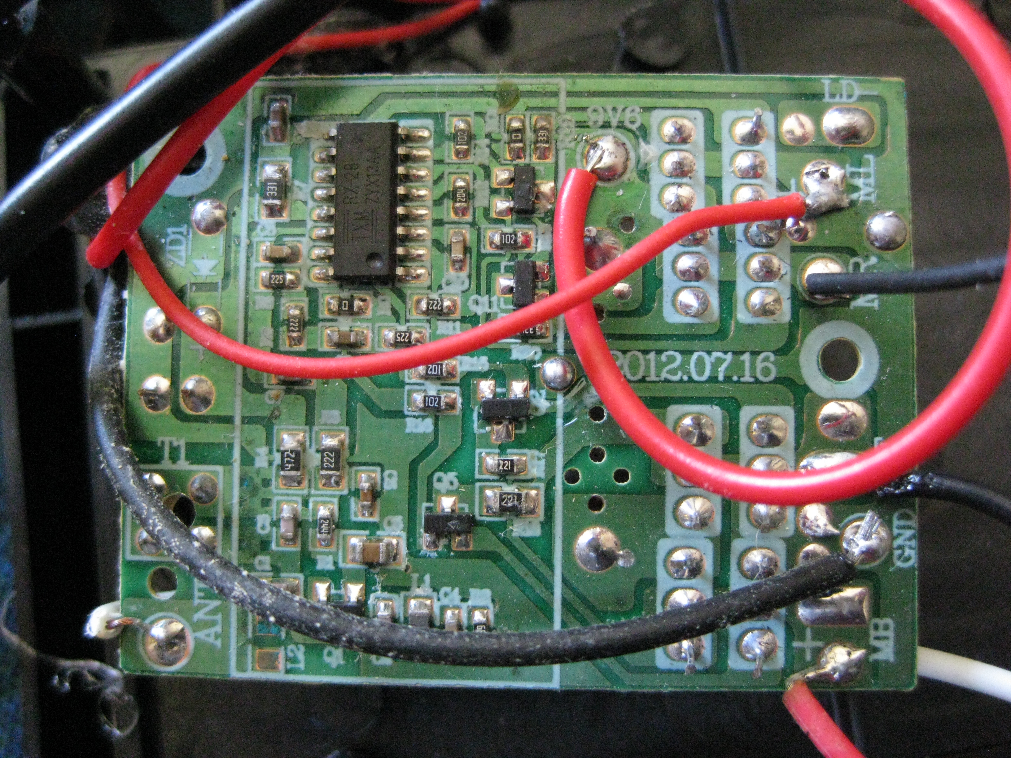
Here is a pic of ther rf reciever in the car. I can see there is a transistor hbridge on the right. The board is powered by 9.6V. How do I tap into this with an arduino, or from the Beagle Bone Black GPIO?
What is the voltage going into the two H-bridges from the control chip? I'm wondering if there's a voltage regulator taking the 9.6V from the battery down to something like 5 or 3.3V for the IC on the left and what voltage it's using to turn on the transistors for the H-Bridge. I'm no EE but I would think you could connect the BBB pins to the inputs on the H-Bridge transistors. If I remember correctly the BBB does 3.3v so that might not be enough to turn the H-Bridge on, in which case you need to use some relays or transistors to interface a higher V input.
When it gets to the input of the H-bridge - it out of some control circuitry, and typically that is always regulated (typically) ...
Find out what kind of H-bridge you have. Specifically the input control. I categorize them this way.
Most have 2 control lines per motor.
The cheap/inexpensive ones are are "smoke-able" - pulse 1 line and the motor goes in one direction - pulse the other line and the motor goes in the other direction - pulse both lines and the motor controller goes up in a puff of smoke - depending on how fast you pulse the line determines speed
The ones I like (and have built) are "smokeless" - 1 line is speed and the other is direction - you only pulse the single line, the direction can be either forward or reverse and there is no way you can smoke it
My bet is that its "smokable"
Ya .. I could believe the bottom picture is the 2 H-bridges - 4 transistors each
How are they connected. If your careful - you can place a multi-meeter on the input and see what the voltage is when its running & stopped - decode the input and see what voltages they are
looking at the board pictures and the silk screen I think it's a smokable arrangement. if you look in the middle you can see 4 surface mount transistors that are probably taking the 3V output from the IC and driving the inputs on the H-Bridge transistors. That seems to correspond with the receiver diagram in the link I posted under the section titled "Interfacing relay to the RX-2B output". They're using the output from the IC to flip a 2N2222 transistor which is driving a 9V relay where as the board Raver has is an H-Bridge input rather than the relay.
The H-Bridge sections are labeled MB MF ML MR which are probably Motor Back, Motor Forward, Motor Left and Motor Right. The input lines look like they're the one's closest to the top and bottom edges of the PCB in the images since they're not tied with the 9V and GND. Just need to see if the inputs on teh h-bridges need to go high or low or you can try tying your GPIO pins to the inputs of the tiny SMD transistors that the IC uses. How good are your soldering skillz? ;)
Good Eye KMC - the MB MF ML MR is the key. Raver wouldn't even need to solder. just cut the lines and splice in a third to go to the BBB
But to be pragmatic, I'd monitor the 4 lines to see what the voltages & frequencies are when its running and stopped. Then just adjust accordingly connect to the BBB & you'll have BBB & RC control .. WOOHOO !
I was thinking that the 4 wires running from M[BFLR] are running to the poles on the motors themselves and thus would be at 9V when running. Are you suggesting that he splice in the BBB to those wires? I would think that would be a smoke emmiter? I'm thinking tapping the pins on the IC is safer assuming they are 3V too.
In the image below I've traced IC pin 7 through a small transistor to one of the H-Bridge transistors. I would test the voltages at both ends of that purple line. I'm guessing the left end is 3V and the right is 9V but it has been a long time since I've dabbled with voltage and current flows through transistors.
Here a article is showing about RC receiver which is used in cars for control the car. It is a digital technology invented for the safety of the car user. There is a radio transmitter which receives signals from outside. The main benefit is to warn the driver at the time of accident. It is the tool which is accepted by almost all the car industries for fulfilling the wants of the customer. The receiver is very sensitive & needs to be operated carefully.

input voltage
What is the voltage going into the two H-bridges from the control chip? I'm wondering if there's a voltage regulator taking the 9.6V from the battery down to something like 5 or 3.3V for the IC on the left and what voltage it's using to turn on the transistors for the H-Bridge. I'm no EE but I would think you could connect the BBB pins to the inputs on the H-Bridge transistors. If I remember correctly the BBB does 3.3v so that might not be enough to turn the H-Bridge on, in which case you need to use some relays or transistors to interface a higher V input.
Looks like 3V
I found this page for the RX chip
http://www.circuitstoday.com/5-channel-radio-remote-control
"Zener diode D1 and resistor R12 forms an elementary Zener regulator for supplying the RX-2B with 3V from the 9V main supply."
KMC is right
When it gets to the input of the H-bridge - it out of some control circuitry, and typically that is always regulated (typically) ...
Find out what kind of H-bridge you have. Specifically the input control. I categorize them this way.
Most have 2 control lines per motor.
The cheap/inexpensive ones are are "smoke-able" - pulse 1 line and the motor goes in one direction - pulse the other line and the motor goes in the other direction - pulse both lines and the motor controller goes up in a puff of smoke - depending on how fast you pulse the line determines speed
The ones I like (and have built) are "smokeless" - 1 line is speed and the other is direction - you only pulse the single line, the direction can be either forward or reverse and there is no way you can smoke it
My bet is that its "smokable"
Ya .. I could believe the bottom picture is the 2 H-bridges - 4 transistors each
How are they connected. If your careful - you can place a multi-meeter on the input and see what the voltage is when its running & stopped - decode the input and see what voltages they are
BTW - relays are find for
BTW - relays are find for direction control - but would not work well for speed control - as you need something that can switch at 32Khz or faster ...
Here's some nice voltage
Here's some nice voltage shifting circuits .. but I doubt if you'll need them ..
http://www.daycounter.com/Circuits/Level-Translators/Level-Translators…;
Smoke em if you got em.
looking at the board pictures and the silk screen I think it's a smokable arrangement. if you look in the middle you can see 4 surface mount transistors that are probably taking the 3V output from the IC and driving the inputs on the H-Bridge transistors. That seems to correspond with the receiver diagram in the link I posted under the section titled "Interfacing relay to the RX-2B output". They're using the output from the IC to flip a 2N2222 transistor which is driving a 9V relay where as the board Raver has is an H-Bridge input rather than the relay.
The H-Bridge sections are labeled MB MF ML MR which are probably Motor Back, Motor Forward, Motor Left and Motor Right. The input lines look like they're the one's closest to the top and bottom edges of the PCB in the images since they're not tied with the 9V and GND. Just need to see if the inputs on teh h-bridges need to go high or low or you can try tying your GPIO pins to the inputs of the tiny SMD transistors that the IC uses. How good are your soldering skillz? ;)
Good Eye KMC - the MB MF ML
Good Eye KMC - the MB MF ML MR is the key. Raver wouldn't even need to solder. just cut the lines and splice in a third to go to the BBB
But to be pragmatic, I'd monitor the 4 lines to see what the voltages & frequencies are when its running and stopped. Then just adjust accordingly connect to the BBB & you'll have BBB & RC control .. WOOHOO !
You want your scalpel now doctor?
ITS TIME TO CUT !!!!
The wires?
I was thinking that the 4 wires running from M[BFLR] are running to the poles on the motors themselves and thus would be at 9V when running. Are you suggesting that he splice in the BBB to those wires? I would think that would be a smoke emmiter? I'm thinking tapping the pins on the IC is safer assuming they are 3V too.
In the image below I've traced IC pin 7 through a small transistor to one of the H-Bridge transistors. I would test the voltages at both ends of that purple line. I'm guessing the left end is 3V and the right is 9V but it has been a long time since I've dabbled with voltage and current flows through transistors.
Your right ! DON'T CUT
Your right !
DON'T CUT THERE !!!
:) - I didn't do the mental jump of realizing the bottom picture is the backside .. for some reason I was thinking they were 2 different boards.
Ok .. make more sense now :P
so from "new" perspective its like a darlington switch ... IC -> bias resistor -> smd Transistor -> bias resitor -> Power Transistor
Would be good if the output of the ic pin there is 3.3 V .. heh ya how's your smd soldering skills AHAHAH !
RC Receiver
Here a article is showing about RC receiver which is used in cars for control the car. It is a digital technology invented for the safety of the car user. There is a radio transmitter which receives signals from outside. The main benefit is to warn the driver at the time of accident. It is the tool which is accepted by almost all the car industries for fulfilling the wants of the customer. The receiver is very sensitive & needs to be operated carefully.
Mini Cooper Repair Millis, MA