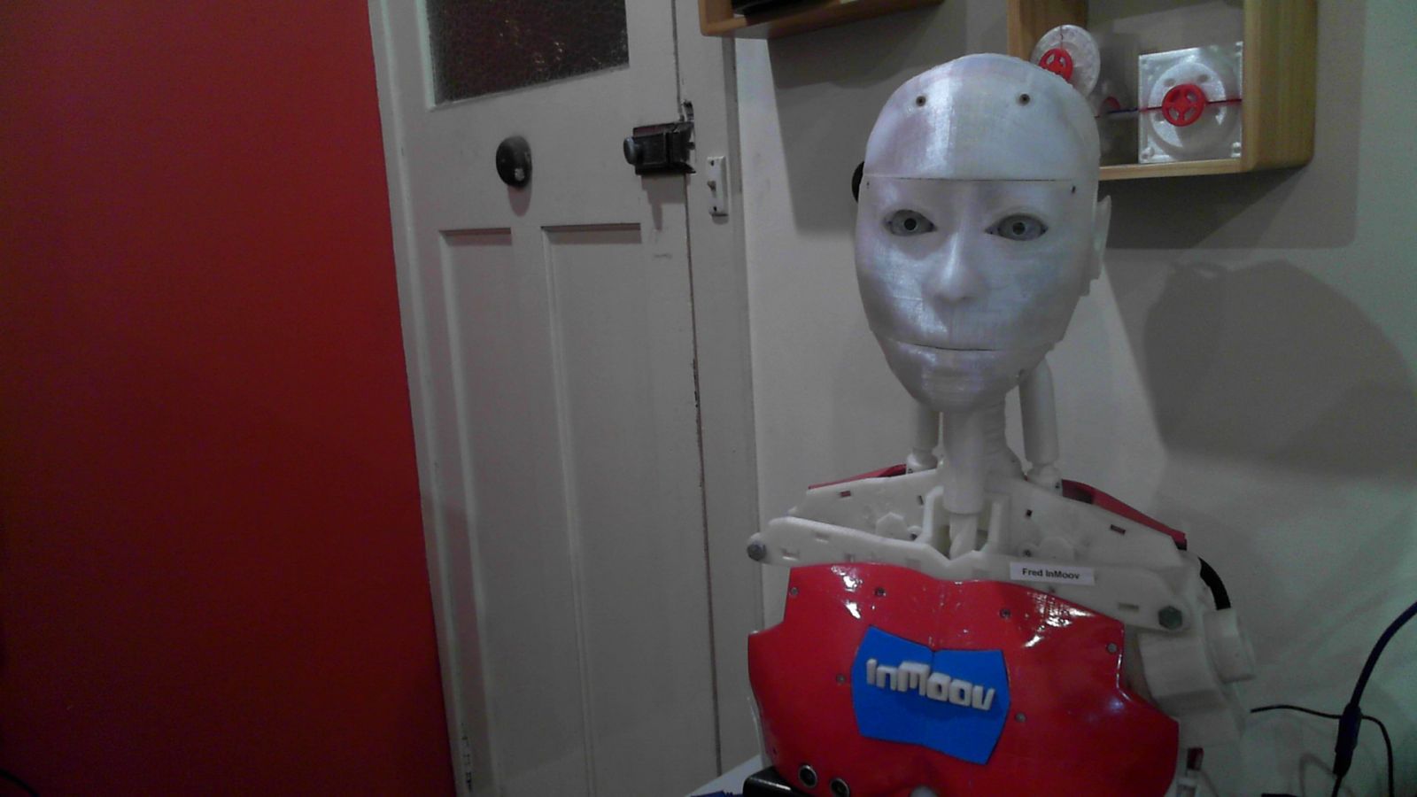
Frequently Re-Engineered Device (FRED)
Fred is a modified InMoov Robot.
You can find the videos showing his contruction here:
In the Official build of InMoov, http://inmoov.fr/
there are two Arduino Mega 2560's located on his back with the I/O distributed using the Nervo Boards available from the online shop in the Inmoov website.
There was also a 8" Lenovo Windows based tablet that running the Java based MyRobotLab http://myrobotlab.org/ that remotely operated the two Arduino Mega 2560's
Because I like to be different, I used the PCA9685 I2C 16 channel PWM driver boards based on the Adafruit servo driver breakout board.
4 of these in various places throughout the robot provide the servo control while reducing the nuber of wires running about the robot.
Lets look at Fred in more detail.
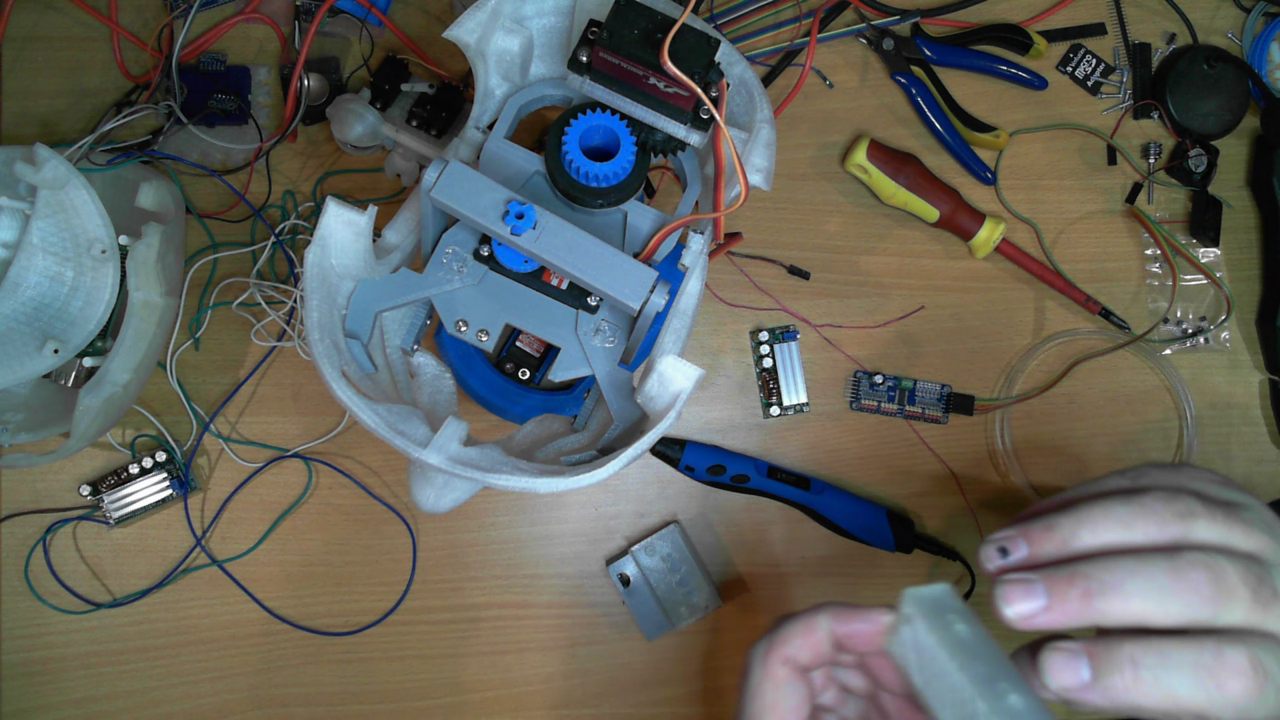
The head is where most of the modifications have been made.
The large Hitech 805BB servo was replaced by a smaller JX Servo PDI6221MG and moved to the back of the skull and turned sideways.
The Jaw servo was relocated turning it over and also moving it sideways.
The eye mechanism was replace with the Dakota76 Advance Eye Mechanism, this has 6 servos with upper and lower eye lids.
With the changes made, there is now enough room in the skull for a Raspberry Pi 4, a PCA9685 Servo Driver and two Switched mode Power Supplies (SMPS) dropping the 20Vdc main power supply down to the 6V for the PCA9685 and 5,1V for the Raspberry Pi.
I used the new neck from the Inmoov.fr site by Gael, this one is far stronger that the other derivative from bob Houstons articultaed neck design.
The downside was because of the modified jaw design and the placement of the SMPS for the PCA9685, I had to extent up the neck mount a bit.
The result is a bit taller neck than normal, this adds close to an inch of height.
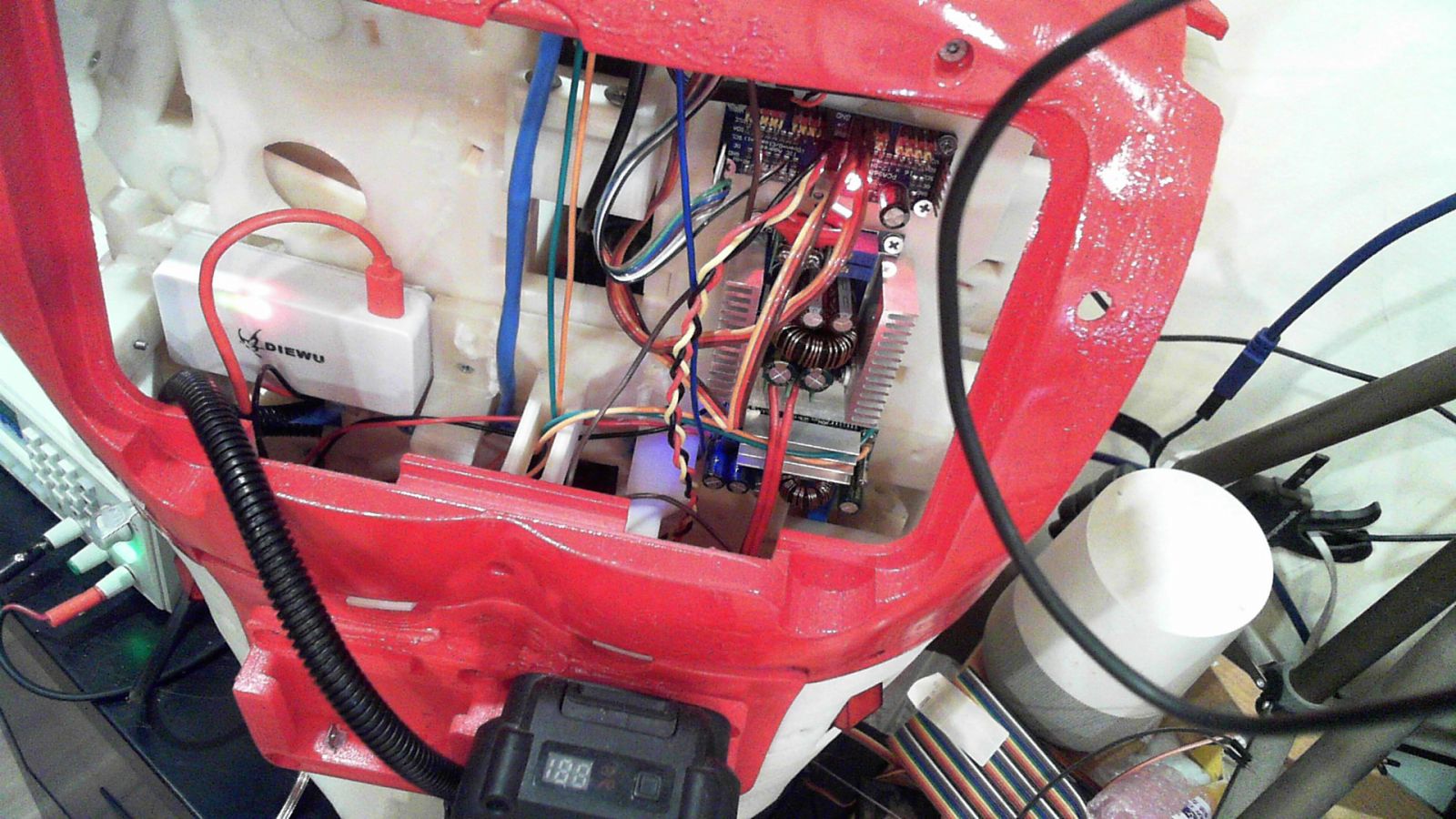
Another PCA9685 is located in the back to driver the servos in this area.
Because a lot of these servos are of the larger type, I've used a 20A SMPA to drop the 20Vdc to the 6Vdc for the servos.
I also have a smaller 3A SMPS to power a small 5 port network switch and a second Raspberry Pi located on the back of a 7" LCD touch screen mounted where the original 8" tablet was.
I will be adding two more 20A SMPS, one in each arm to power the servos in the elbow and hands.
One of the most common questions I get about Fred is why am I using 20Vdc in his power system.
The answer to this is to avoid as much power loss as I can.
Fred did make a video on this subject: https://youtu.be/2HXUAxqaLt4
Power = Volts x Amps.
Volts = Amps x resistance.
Power = Resistance x Amps X Amps.
What a lot of people don't understand is that all wire has a resistance, granted its normally very low, but its there.
The larger the diameter the wire, the lower the resistance, but the longer the wire, the higher the resistance.
If you have a current flowing through a resistance, Ohms Law states there will be a voltage across that resistance.
If you multiply the voltage with the amps flowing you get the power lost in that resistance. This is power loss.
If you have a servo running 6Vdc at 2.5 Amps, it will be consuming 15 watts of power.
If you have small wires running a sizable distance you can get quite a voltage drop in the power wires feeding the servo, enough to drop your 6V supply down to 5V or less at the servo this is a 2.5 Watt loss in power that your servo is not getting.
To complicate the matter further, motors will automatically adjust there impedance (think of this as a changing resistance) to get the power they need to rotate the load.
So if the voltage drops, then the motor needs to increase the current to get the same power.
If the impedance drops to the resistance of the servo and there is still not enough power to turn the motor, the result will be a burned out servo motor.
To overcome this problem, I'm keeping the length of the 6Vdc low voltage supply as short as possible, resuding the resistance of those power wires. (Shorter wires, lower resistance, less power lost)
Using a higher voltage, means a lower current for the same amount of power.
At 20Vdc, I end up with 1/3 the amount of current flowing in the supply wires running throught the robot.
Because the power lost is the wire resistance x Amps squared, that works out to be a significant power saving.
It also means the wires don't have to be overly large.
Bigger wires also weight more and are not as flexiable.
So there are a few benifits to a higher voltage distribution system.
There is a good table for wire sizes, current capacity and the resistance of the wires at Wikipedia here:
In version 5 of the program I'm using to run Fred, I split the single script up into a number of files and expanded on the comments to help better explain what is happening.
With a bit of luck you will be able to follow along and learn more about how MRL works.
All of the programming I've done is in Python which will make it easier if you want to use this program and need to add to it.
You can find the program here on GitHub: https://github.com/Cyber-One/Fred_Inmoov
If you have any questions regarding any of the files here, drop into my Discord and ask your questions, hopefully I will be able to answer the questions or implement changes if needed. :-)
There is a whole series of video on Freds construction, you can look at the PlayList here:https://youtube.com/playlist?list=PLgXTfFM40HqEbnFfhaLPmLv_RS1ZRCilI
I hope to make a series on Fred program as well.
Ray
Very nice progress Ray! I
Very nice progress Ray!
I have been watching all your video's since you started, and I must say you do an excellent job at explaining and teaching the process of your build.
It's always a pleasure to see different builds.
Cheers!
Easy to teach with a good platform :-)
It really is a good platform to learn and teach with, and there is so much protential with it and for that I am greatfull to you for your designs.
I can see going into the future there will be many more upgrade and redesigns as we learn more.
Like a lot of people I'm still tinkering away at walking legs.
I'm hoping you can make them look as good as the rest of the bot when we get them to work :-)
In the mean time, all I can do is try and help our budding engineers learn more about how robots work.
There are a few builders who also try and so and teach how to build this great robot.
Kyle Campbell, Steve Rayner are the first two that come to mind.
I don't know if you have seen the InMoov Robot Builders group on Facebook headed up by Shido Xen, he's done a power of work in helping to guide builders with his diagrams.
There is also a Discord group, Robotics Learning with a big focus on the Inmoov robot. https://discord.gg/YvvMC4hUX9
It really is amazing the size and scope of the builders of this great robot, and for the most part, they are all good people.
Just goes to show how a great design can bring people together from all over the world.
Good job :-)
Ray
Low Latency High Resolution Video Stream From RasPi
Great Post Ray.
For my RasPi I've been playing with this set of dependencies:
sudo apt-get -y install gstreamer1.0-tools default-jdk sshfs alsa-utils gpac alsa-utils gphoto2 v4l2loopback-utils v4l2loopback-dkms ffmpeg mpg123 festival espeak mplayer espeak-ng git maven wiringpi
And for me the following command works best:
On the RasPi:
It's using netcat the network super utility tool.
On another Linux host I do:
I don't think fps matters so much on the client side, it can only display new frames when it gets it, so in general you want it higher than what the actual fps is streaming from the raspi. I'm using ether on a fast local Lan using a TL-SG108 and getting 1280x720 subsecond latency.
A very cool feature is MRL can decode the stream using the FFMPEGGrabber
So on my Linux Host doing this in MRL
.png)
gives me
It has more latency ... about 1 to 2 seconds ...
but filters can now be applied ... Yolo Canny etc...