By chatting in the shoutbox, it came out the problem of the mic picking up too much noise from the servos. In order to try to reduce or eliminate the problem my suggestion (which I will try by myself as soon as my robot head will be finished) is:
1) abandon cardiod-shaped diagram microphones (those which you are using at 99% of chances) adopting monodirectional, shotgun-shaped diagram microphones.
As you can see from the polar diagrams the cardioid (green diagram) picks sound from the front, side and back (a lot). The shotgun microphone (red diagram) pics sound mostly from the front and very little from the side and the back.
The shotgun microphone should be incapsulated in a styrofoam encase, in order to further minimize the amount of sound coming from the side and from the back.
This should be enough to dramatically lower the amount of noise picked from the servos.

If we want to make things better, we could use two shotgun microphones. This will allow the robot to understand the direction from which the sound is coming as the servo noise will be equally distributed between the two microphones but the environment sound will arrive time shifted (and phase shifted as well) between the two microphones. Proper algorithms can reconstruct the incoming direction.
Shotgun microphones are long and stretched, but there are some miniature models as well which can be easily fitted within the head, or if not possible, within the chest.
If we want to make things even better, we might stick a single piezo microphone directly attached to the mainframe of the robot. Piezo microphones are usually rounded and flat metal discs, this makes it easy to be properly placed against the robot internal frame.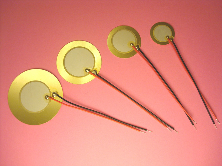
The idea is to pick up as much servo's noise as possible, through such microphone, amplify it and then subtracting it from the signal coming from the shotgun microphones. The downside of such type of mics is that they are usually poor in getting low frequencies while the servo's noise should be well below 1 khz. Because of that the signal must be low-band filtered before the amplification.
The idea is to have (shotgun mic signal * preamplification) - (piezo mic signal * low band filter * preamplification) = environment signal
This can be achieved through mathematical elaboration of the signal (see paper below) or by mixing the two mic signals with an operational I.C.
This is a paper which might be useful, as somebody addressed the same "robotic" problem before us: http://hal.inria.fr/docs/00/86/14/65/PDF/main_final.pdf
A futher way to implement speech recognition is to apply a notch filter after the preamp or a bandwidth filter before the preamp, being it hardware or software
Just my 2 cents, as soon as I'll be ready with the robot head, I can help with the tests.
Sink them into tubes
You could always sink the Piezos onto the bottom of open tube/dish lined with foam.
Thanks for the excellent
Thanks for the excellent post. Exceptional information, thanks for sharing!
I thought it would be nice to get directional information from the sound, sadly almost all computer sound cards are mono on mic, but "input" I think is dual channel. Looking on my laptop now, it only has a "mic" analog input - so I'm betting it is single channel.
I would imagine that you can get stereo mics which connect either bluetooth or usb - the problem is they will most likely have properitary drivers.
Borsaci came up with a hardware solution - don' t know how well it worked, but he is clever.
Just looking around for Stereo DIY Mics I found some interesting projects, albiet not as relevant as I had wished.
Direction DIY Microphones
DIY Microphone Arrays
Stereo recording is obtained
Stereo recording is obtained using the proper drivers and a proper audio interface. There are cheap audio interfaces around which for a few bucks, you get stereo recording. Audio drivers should also be substituted as the normal windows drivers have a too high latency (I use ASIO or ASIO4ALL drivers).
Servo's noise frequency test
As you can see by the video i made a test by checking the sound produced by the servos in three different setup (in my hand, on the table and attached to Inmoov's skull, to replicate eventual resonance phenomenon).
The servos are producing the noise peak around 250Hz and have a noise distribution throughout all the spectrum, but the most energy is between 0Hz and 800Hz-1Khz.
In the test I run just the servo's noise alone first (moving continuosly the servo from 0 to 180 and back) and then the same noise with a superimposed voice track.
I applied then a wide notch filter, working from 0Hz to 1,6Khz and rerun the superimposed voice track.
The results are quite evident, the voice can be still heard and the noise is much quiter.
This is due to the fact that human voice has two major formant frequencies. The first one is TOTALLY covered by the servo's noise frequency. Fortunately the human voice has a second formant at a much higher frequency than the servo's noise one which is between 2Khz-3Khz
Then we could improve speech recognition by:
1) use shotgun directional microphones, encapsulated in a sound absorbing case
2) cut off with an electronic or software filter all the frequencies between 0Hz and 1,6Khz
3) mathematically subtract the servo's amplified noise captured with a piezo microphone from the main microphone signal.
Operation 2 and 3 can be done both electronically or via software analysis.
PS: speech recognition should be turned off during the "did you say?" phase to avoid Inmoov listening to its own voice.
Great experiment. I would be
Great experiment.
I would be concerned about latency in software too. You have already replaced standard operating system drivers because of latency.
If your filtering those frequencies out with bandwidth filters, why is the power levels still the highest in the lower end - even with the filters applied? Shouldn't they be gone? I did hear it as diminished, but my expectation was thinking it was going to be nearly gone. What filters are they exactly? Are they a multitude of narrow band filters?
Regardless - great info.
Also, speech recognition "should" be inhibited at any time InMoov is speaking... that's the way it was designed, but I'm not positive about the quality of the implementation..
The spectrum analyzer in the
The spectrum analyzer in the video was chained before the equalization, so regardless the equalization settings, the analyzer shows always the original sound spectrum. I didn't think it was relevant to show the spectrum after the equalization, I thought it was enough to hear the sound difference.
The applied filters are narrow band filters, the reason why the servo's noise was not entirely gone is related to harmonics.
The servo's sound is mainly located around 250 Khz but its harmonics proceed up to the upper end of the spectrum, where the second human voice component is present. Eliminating those harmonics with narrowband filters would also eliminate the voice.
This is why in my opinion it would be better to use a piezo mic to pick up the servos buzz to be later subtracted from the environmental signal
I think that is a great idea.
I think that is a great idea.
Sample and filter
Hi Roberto / Grog
I have been thinking about this problem a bit. I think that people will have different types of materials, different voltage levels, and even different types of servos. These will all contribute to a different filter that is optimimal for the noise elimination / reduction.
I believe that something like and adaptive filter would be best. The idea is the robot can listen to itself in it's environment. Record the spectrum of the ambient noise. This noise could then be "subtracted" from the original audio input.
If you are framiliar with Lapalace transforms and convolution this will probably make more sense... but here it goes.
x(t) ->( h(t) ) -> y(t)
for a given input signal x(t) we can pass it through a system and the resulting signal will be y(t)
the relationship between the input x(t) and the output y(t) is defined by "some filter" defined by it's impulse response waveform h(t) . With this model , we can represent the ouput of this as a function of it's input and it's filter. This is convolution.
+
y(t) = | x(T) * h(t-T) dT
-
With this relationship we can define how the output signal is changed given noise convolved with the input signal...
So, if you can determine what "h(t)" is this characterizes the noise in the communication channel. If we take the inverse of this h(t) ... we can create a filter that perfectly charactizes the noise that comes from the servo motors.
This is easier (and probably faster) to do in the frequency domain. So if we take the FFT (Laplace) transform of the system to look at the spectra of it we end up with the following model
X(S) -> H(S) -> Y(S)
That is the output Y(S) is the input X(S) times the impule response of the filter H(S)
Y(S) = H(S) X(S)
This is a simple multiplication in the frequency domain..
The goal is to get back the original signal X(S) given that we observed Y(S) ... so we should be able to do some fancy math given this relationship and end up with
X(S) = Y(S) / H(S)
Or we see here that the input signal is the output signal convolved with the inverse of the impulse response....
.... So.. long story short..
If if can find out what 1/H(S) is for the current environment,... we can create a digital filter that approximates that ...
Once we have that digital filter, (or analog would be very cool) we can apply it to what the robot hears. and presto, the signal should be cleaned up... (assuming the ambient noise doesn't change dramatically)
So.. ok. I know that was probably very drawn out, but my gut tells me that this (assuming the mathmatical is correct) will provide the robot a way to adaptively drown out background noise and noice from nearby servos. It should also allow for a cycle to be able to calibrate it..
Thoughts / Comments are welcome...
-Kevin