Hey all! THE BUILD-UP IS DONE! Here's the latest pics, including my first print ever! Below is the last of the Rostock MAX building pics... hopefully soon I will be posting InMoov android pics in it's place.

Above, wrapping the resistors with aluminum foil to make for a tight fit when mounting. Failure to do this will keep the hotend from conducting heat away from each resistor, and they will surely burn up! The tiny 100K Thermistor that tells the computer exactly what temp the hotend is lies below.
Below, both resistors wrapped and installed in their holes. Yup, you purposely overheat resistors to heat this hotend, and it works well. The wires are twisted on each end, making a parallel circuit. ABS extrudes at around 230C.

Hotend finished and ready to mount. I added good plugs to both the Thermistor and the hot end resistors to make it easier to remove and repair or replace.

Here's the almost finished extruder. Wires still need to be extended, but it's looking good.

My first print ever... First time ya just pray that the nozzle doesn't come crashing into the build surface. BTW, my build surface is Lexan, heated to 75C for ABS...AND BOY DOES IT STICK! A small fan mounted on the left can blow over the insulator on the hotend to keep it cool.

The finished Calibration cube... It might be ugly to you, but it's a beauty to me! Whooooo Hooooo!

Below, IT"S DONE! Or at least done as a cutting edge printer ever gets... I'm already planning to add a few things... New spool shaft, etc. There is a real learning curve to this technology, but it's a lot of fun when things go right.


UPDATE: 3/11/13
Pictured above is the platform U-joints being test fit. You must sand or file away at the joint until it's just a snug fit. Below is the platform with delta arms snapped on. Pretty! The Hotend will mount here.

Below: Building the acetal bearings. You must deburr and smooth the edges. The contact area is perfect out of the mold.

Finally! The Rostock MAX with arms and platform. Now we're getting somewhere!

Our last pic is the "Cheapskate" (SeeMe CNC name, not mine!) assembly. You would be suprised at how nice this rolls up and down the aluminum extrusion. It's adjusted by eccentric cams, or by an eccentric me...

3/7/13:

ShownAbove is the Hot bed, after soldering the LED and it's dropping resistor. This lets you know power is applied to the bed and it is heating. Normal bed temp. is between 60 -100C. Also visable are the large pads provided to solder the bed heat wires, both top and bottom.
Here the Thermistor has been soldered to it's pads at the center of the bed. Teflon tubing insulates against shorts.

A dab of black RTV secures the Thermistor. The bed support has a hole to allow the bed to be mounted without interfering with this sensor.

There are large pads to solder the bed power wires, both top and bottom. I chose to wire two 18ga. to each pad, for a total of 4 18ga. wires to each positive and negative side. This helps conduct the needed current for the large bed. The small white wires at left are the leads from the Thermistor mounted at board center.

Here we see the Rostock MAX with it's extrusions mounted for the first time. They are easily secured by four T-nuts top and bottom. The Hot bed has been permanently mounted. Things are coming along!

I have opened the electronics bay to show the RAMBO board, and some of the wiring that leads into this area. Soon connectors will be installed and plugged it. The design allows for easy access to almost everything, and seems to be very well thought out...

3/4/13:
Here is the base, ready to install the nuts that secure the top, followed by the top.

The base has two swing out doors in order to install and access electronics and internal wiring.

Here's the base with top installed. Visible is the power supply which powers the unit and bed heater.
.jpg)
Here you can see the custom heated build platform, currently just laying on base top. Diameter is 280mm!

2/28/13:
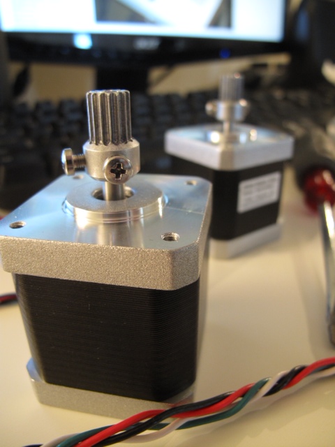
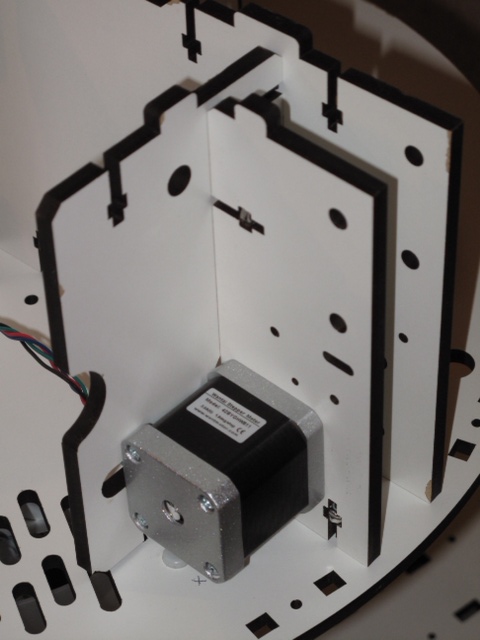
Pictured are the Stepper motor crimped connectors, and the base with the supports and motor mounts. As the pictures show, the pieces are connected by installing Nylok nuts in each upright, then through bolting with small flat headed screws. Everything so far is extremely high quality, and basically snaps together. One of the Stepper motor's wires must be extended with the included wiring, then the connectors are crimped on. I chose to solder and heat shrink, but you could use small (red) butt splices too. More to follow..


.

Looks Great !
I'm excited to see this in action...
Is there an online assembly guide ?
Absolutely! Here's the Wiki.
Absolutely! Here's the Wiki. There are downloadable PDFs for everything: http://reprap.org/wiki/Rostockmax
It's Bigger !
Is the power supply a standard ATX ? It loks like it from behind, although I wouldn't think they would need much 5V..
The steppers are 12V?
Yup, ATX. The bed and I
Yup, ATX. The bed and I believe the steppers are 12V. The design is VERY well thought out...
To enclose or not to enclose - that is the question
it seemed like Gael was pretty adamant about an enclosure - I can imagine the whole thing in a giant plexi-glass tube, in a dark room, with blue led lights at the top ... now that would just look cool - right out of sci-fi movie...
Oooh... maybe some smoky mist too for effect ;)
As long as the smoky mist
As long as the smoky mist isnt something burning up I'm down with it... ;-)
It's doing great, Chris! I
It's doing great, Chris! I love to see the construction. Parts are very clean and well designed. Can't wait to see it print.
Print Print Print !!! It
Print Print Print !!!
It looks great, your photo docs are appreciated.
Can't wait to see it print!
Can't wait to see it print!
How much time do you estimate
How much time do you estimate the whole build process? Did you go through wondering steps that could affect the end result, or is it all pretty straight forward? Do you think it is doable by a lot of DIYers?
Ahhh, there a good question!
Ahhh, there a good question! I think you could build one in about four full days, if you worked solid. I worked on and off, trying to enjoy it as I went. Some steps are easy and a blast, others not so much. A DIYer with skills in soldering, modeling, and some pretty good computer skills can pull it off. SeeMe CNC has a great forum to ask questions in, and several good threads from people who have documented their entire build-ups. Some parts are challenging for sure, and you must understand that these Delta machines are first generation cutting edge. There is a learning curve here, just like when you started, I'm sure. Before starting, I would buy soldering equipment, 15mm Kapton tape, heat shrink tubing, and a tube of RTV silicone. You also need a few crimp cap type wire connectors, and some patience! Hope this helps, Chris
Cubie !
You did it .. your father of a baby Cube... and look how cute Cubie is ! Looks great.. fine straight standing fellow !
Great Work !
I really have to admit with
I really have to admit with Grog, this a cute little cube!
The way you have handled building up this printer is pretty reassuring about your skills to do clean work! The parts of this printer are very well made, it doesn't look cheap at all.
Now comes the printing process and learning. Is that Lexan surface you are printing on, easily swapable by another one? it would greatly help cooling time between prints. Does the lexan gets residue or scrashs after the print, due to too much sticking? If yes, you could lay a surface of Kapton applied with a spatula. Spatula applies it very cleanly, doing only by hands gets you bubbles under.
Hey Gael! Thank you so much
Hey Gael! Thank you so much for the compliments. It truly means a lot, coming from you. For a kit, the Rostock MAX is very well engineered, with several injected plastic custom pieces and a custom 300mm (12") heated bed. When parked at the top stops, there is 363mm of build height below (14.5"). Actual buildable height must be less, but it's still the tallest build height I have ever seen in a printer.
As for the Lexan build plate, it seems to be amazing. The ABS stuck like glue at a bed temp. of around 75C, (and the guys at SeeMe CNC say it can be run down to 60C) and after I let it cool for a couple of minutes, you unclip it and flex it and the part pops right off. The Lexan is roughly 3mm (1/8") thick, and so flexes easily. The only piece I have printed so far left no marks at all. We'll see how it works in the long run. I'm am going to experiment with Kisslicer next, as it has features that favor Delta design with a Bowden type remote extruder. All I need is time, as I have two job interviews coming up... Ciao, Chris
I use Kisslicer for my
I use Kisslicer for my slicing, I just love it. The BFB printers come with a software called Axon which is closed source. Axon takes 15 to 20 minutes to slice an stl, when Kisslicer takes 1 or 2 minutes. This is not overdoing at all! Kisslicer simply slice, if you see you did something wrong in your preferences choice, you just re-slice. Axon in the meantime is still slicing the first quart of the stl...
I know I bit the guy who has created Kisslicer, Jonathan, if you need help at some point let me know. I don't think my settings could be of any use for the Rostock, but who knows.
Rostock
Hey Fabrice! Gael told me
Hey Fabrice! Gael told me about you. I hope all is going well so far with your Rostock build-up. When you build your platform and attach your arms, pay VERY close attention to fitting them. Make sure that NONE of the joints are tight. You can't have them so loose that there is play in the joint, but they must be free of all binding. This is very important. If they are too tight, you will see it in the way the printer prints the infill... It won't attach to the outside walls of the print. It takes time to get all the joints free but without play. Maybe a full day.... But it's worth it! Chris
Thank's yes it's so long and
Thank's yes it's so long and the difference beetwen the good joint and bad joint is very just
Hi there Chris I have finish
Hi there
Chris I have finish the construction ,But when I want connect the printer with my Macbook with the usb wire the macbook disconnect the usb plug with a message , printer want lot of energy and for the security of laptop the plug is of can you tell me how do you make for your first connection and under power
thank's a lot
Fabrice