I recently saw some posts in the InMoov forum talking about how the supply lines are very important to being able to power the servos properly. My initial reaction was that the resistance of the wires going to the servo motors should be negligable. I mean, after all , it's wire.. it's copper.. it's a conductor. When we think about circuits we always consider that the wires don't have any resistance at all. They're ideal conductors, if you will. In general, for low currents that we typically see in circuits in the milliamp range, the resistance of the wires is indeed negligable...
What a surprise to come to realize that now when driving 40 amps of power to the servo motors of the InMoov, those ideal conductors start showing their imperfections and physical limitations. Indeed, the ideal conductor is just that.. ideal. So it shall be that the fantasy is nearly always better than the reality. Real wires do have resistance... (and probably capacticance and inductance .. but let's keep this simple for now.. as we're really only talking about DC power supplies.)
So.. if a wire has resistance, we should probably model that when we size the power supply. Let's take a simple example. Let's say 1 servo is turning. Let's say that servo is applying a constant torque. A constant torque should be generated by a constant amount of power being driven to the servo. Great! So, if the wire has some resistance, and the servo is drawing a constant amount of current, we can model the servo as a current source that is driving a constant current.
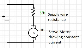
Ok, Here's our circuit. We have a power supply on the left side. We have a wire , we'll model that as a resistor R1. The value of this resistor is a function of the type of wire you are using. Let's say servo "M1" is a servo motor that is drawing a constant 1 amp.
We've all (hopefully) heard that V = I* R
Let's all say it together now.. Ohm.... Yes Ohm's Law. Horray! What does it really tell us. It says a few things.
1. The current into a junction equals the current out of a junction
2. The voltage drop around a loop in the circuit equals 0.
So, we have a voltage V, if we follow around the circuit we'll pass through R1 then we pass M1. Finally we arrive back at the voltage source V. Look at that, we made a loop.. so what's that part about the voltage dropping and equaling zero..
Supply Voltage - Voltage Drop across R1 - Volatge Drop across M1 = 0 ...
Ah, great, so let's say our supply voltage is 5V.
And we know the servo motor is a constant 1Amp.
So, The only connection between R1 and M1 is one wire. That means the current coming from R1 must all be flowing into M1. There's no where else for it to go.
Another way to say that is, all the current that M1 is taking is coming through R1.
So, we want to know what is the voltage that is at the servo motor...
That means we've have to account for the drop across R1. Ohms law tells us the voltage drop is R1 * the current going through it. In our case 1amp for the servo motor. We don't know what the resistance of the servo motor is, so we don't know what the voltage across that is.
Voltage(M1) = V(supply) - I * R1
This is interesting, it says as the current increases,the voltage that gets to the motor will decrease. So, indeed , if the current is low, the votlage at the servo motor will be very close to the supply voltage.
We have thus gained a bit of insight into how circuits get loaded.
So, what size wires to we need?
As it turns out, I've been using 22 AWG copper wire to hookup my servo motors directly to the power supply. Yes, thiat's right, one single 22 AWG (not stranded!) wire. So, how much resistance is the wire imparting..
There's a handy page that can help you compute the restance of a wire based on the length of the wire, the crossectional area, and the material of the wire.
http://www.calculator.net/voltage-drop-calculator.html?material=copper&…
I'm guessing the InMoov draws about 20 Amps when it's fully moving, so I was trying to drive 20 Amps through my itty bitty 22awg hookup wire. Oops... No wonder they were getting hot ( power dissipation is P = /I^2 * R ... that means heat!)
For my situation, when the inmoov started moving, Based on the calculationsfrom that link above, by the time the servo was getting the power, it was already down to about 3.8 volts. And imagine this.. It moves slow! The HS-05BB's need at least 4 Volts to move.. They like as much as 6.
So be continued, I'll be fixing some wiring a bit this evening, and re-routing some of the power. I hope to see a big improvement in the speed of movement and power effeciency of the robot after cleaning up this amature mistake.
This post was inspired by the inmoov forum thread about power supplies.
https://groups.google.com/forum/#!topic/inmoov/3jwBqoN-H6g
To be continued...