There are two common nRF "Mini" development boards available namely :-
The nRF52840 and nRF52832
| NRF52832 | NRF52840 | |
|---|---|---|
| Processor | ARM_ Cortex_-M4 32-bit processor with FPU, 64 MHz | 32-bit ARM_ Cortex_-M4F @ 64 MHz |
| RAM | 32/ 64 KB | 256 KB |
| Flash | 256/ 512 KB | 1 MB |
| NFC | YES (For pairing) | YES (For pairing) |
| Package | 6×5 mm QFN-48/ 3.0 x3.2 mm WL-CSP | 7×7 mm AQFN-73 |
| Operating channel | -40 -85 C | -40 -85 C |
| TX power (Max) | 4dBm | 8dBm |
| RX sensitivity | -96 dBm @ 1Mbps for BT 4.2 | -103 dBm @125 Kbps |
| -99 dBm @ 500 Kbps | ||
| -96 dBm @ 1Mbps | ||
| -92 dBm @ 2Mbps for BT 5.0 . | ||
| Support data rate | 1Mbps/ 2Mbps for BLE and 2.4 GHz | 125Kbps / 500Kbps / 1 Mbps / 2 Mbps for BLE |
| 250 Kbps for 802.15.4 | ||
| 1Mbps / 2Mbps for 2.4GHz | ||
| TX current | 7.5 m A @4dBm DC-DC | 13.6 m A @ 8 dBm DC- DC/ 3V |
| 5.3 m A @0dBm DC-DC | 7.3 m A @ 4 dBm DC-DC / 3V | |
| 5.3 m A @ 0 dBm DC-DC/ 3 V | ||
| RX current | 9.7 m A @ 3V DC-DC | 5.4 m A @ 3V DC-DC |
| Sleep current | 0.3 _ A @system off | 0.3 _ A @system off |
| Serial interface | 2x I2C master/slave | 2x I2C master/slave |
| 3x SPI master/slave | 4x SPI master/slave | |
| 1x UART CTS/ RTS | 1x QSPI | |
| 1x I2S | 2x UART CTS/ RTS | |
| 1x PDM | 1x I2S | |
| 1x QDEC | 1x PDM | |
| 1x QDEC | ||
| Supply voltage | 1.7 -3.6 V | 1.7 _ 5.5 V |
Most of the examples in the Nordic SDK are based on the nRF52832... and only a handful for the nRF52840.
Caution :- If you are using the Nordic Connect App to program the devises over USB Bootloader....beware...
If you try to compile an nRF52832 example and hope its a simple case of programming the nRF52840 with the hex file generated then think again.
You have to alter some options in the Segger Studio :-
Firstly You have to tell it to set up the environment for the nRF52840 :-
Be sure to select the "Common" pull down section....this will ensure that any changes you make will be applied to the Debug & Release settings....as in the wonderment of Nordic mentality they though it a good idea to separate the two...

| Set Preprocessor Definitions |
|
APP_TIMER_V2
APP_TIMER_V2_RTC1_ENABLED BOARD_PCA10059 CONFIG_GPIO_AS_PINRESET FLOAT_ABI_HARD INITIALIZE_USER_SECTIONS NO_VTOR_CONFIG NRF52840_XXAA |
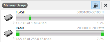
And then because of the differing Memory allocations (Flash size etcetc) to following needs to be updated, these values are working for me for the PWM example (coming soon to MRL studios near you).
Be sure that the Section Placement Macros and the Memory Segments are matching (I spent a whole week wasting time on this one, as its not mentioned in the official nRF52832>nRF52840 conversion tutorial)

| Memory Segments | |
| FLASH RX 0x27000 0x100000;RAM1 RWX 0x20000008 0x40000 | |
| Section Placement Macros | |
|
FLASH_START=0x27000
FLASH_SIZE=0x100000 RAM_START=0x20000008 RAM_SIZE=0x40000 FLASH_PH_START=0x1000 FLASH_PH_SIZE=0x100000 RAM_PH_START=0x20000000 RAM_PH_SIZE=0x40000 |
With these setting the Program will end up sitting at memory location 0x27000.
