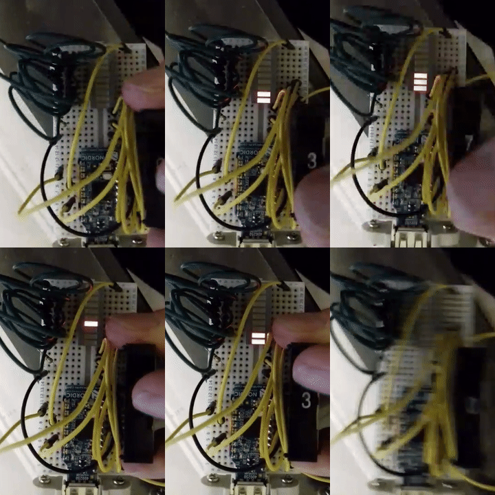

|
Based off the Bog standard "Blinky "Example contained in the NRF SDK :- C:\nRF5_SDK_17.0.2_d674dde\examples\peripheral\blinky\pca10059\mbr\ses\blinky_pca10059_mbr.emProject Load in the project using Segger Studio , Select the main.c file , delete its contents and paste the contents below. Build and send the .hex file to the nRF52840. |
|||||||||||||||||||||
|
/// GPIO inputs
#include <stdbool.h> #define led1 13 int main(void) nrf_gpio_cfg_input(Button1, NRF_GPIO_PIN_PULLUP); nrf_gpio_pin_set(led1); while (true) }
|
|||||||||||||||||||||
|
Should you wish to use the onboard buttons they are active low, which means that the input will be connected to ground when the button is activated. The SW1 button has no external pull-up resistor, but the reset button (SW2) has a 10 k pull-up resistor. To use SW1, P1.06 must be configured as an input with an internal pull-up resistor. The LEDs are active low, which means that writing a logical zero '0' to the output pin will illuminate the LED.
|
