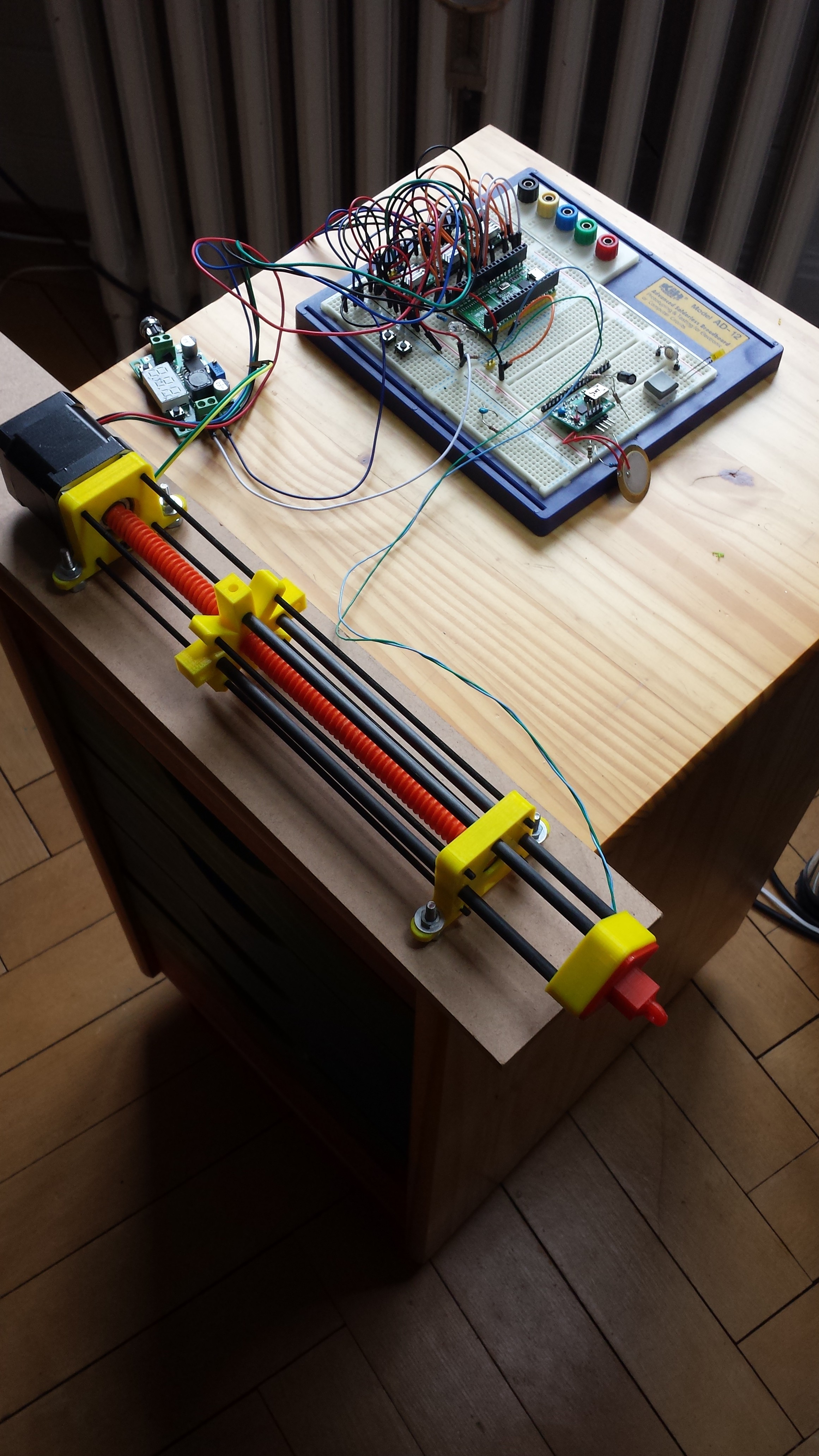
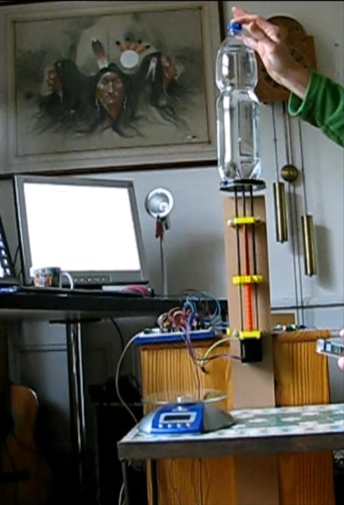
Here is the current working system.
The design 3D STL print files can be found here Chiprobots Thingiverse Channel
Below you see the Nema17 Stepper motor ,Actuator,ESP32,ramps controller birds nest.
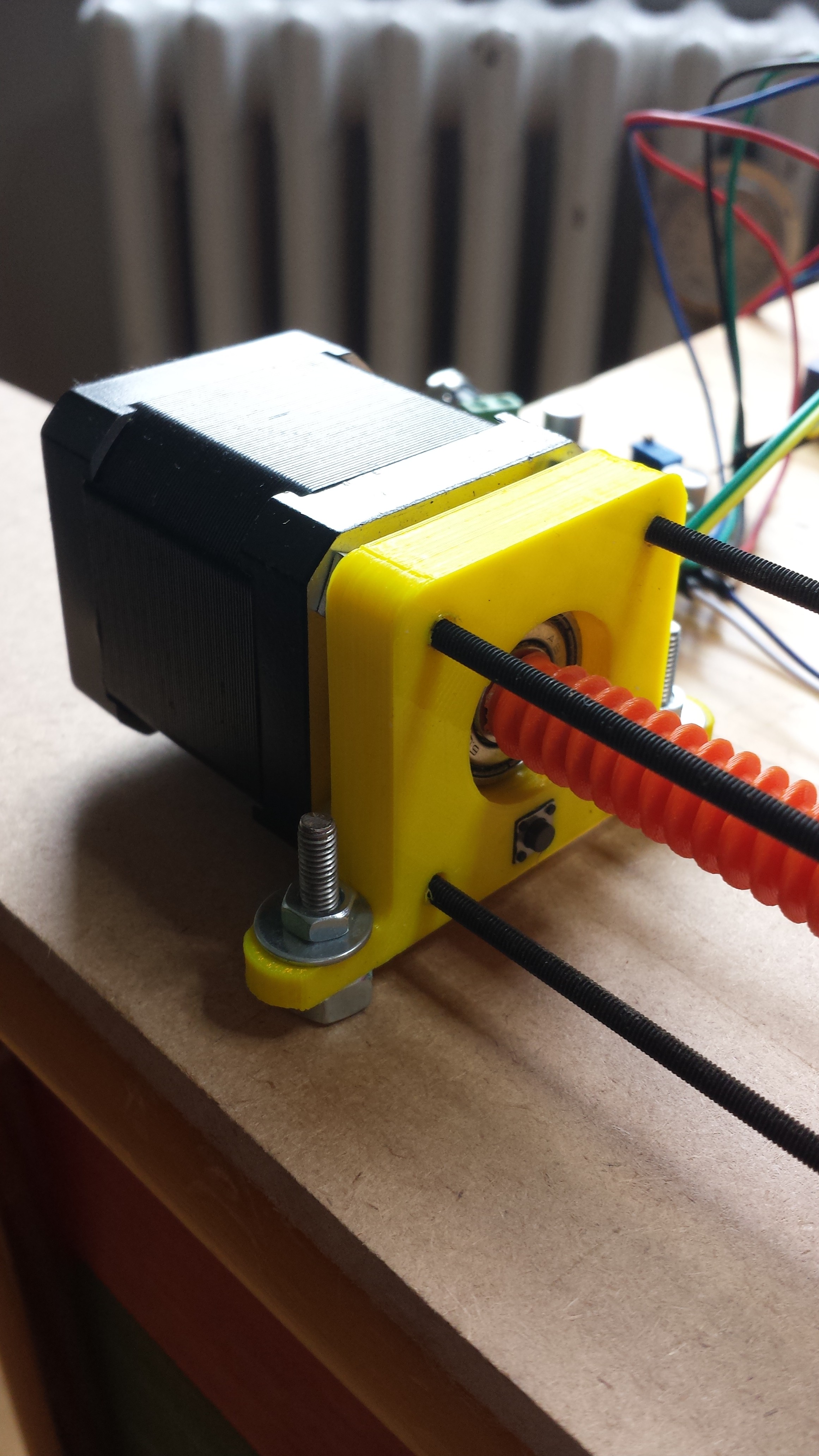
The Nema17 stepper is a generic type (mine is 47mm long).
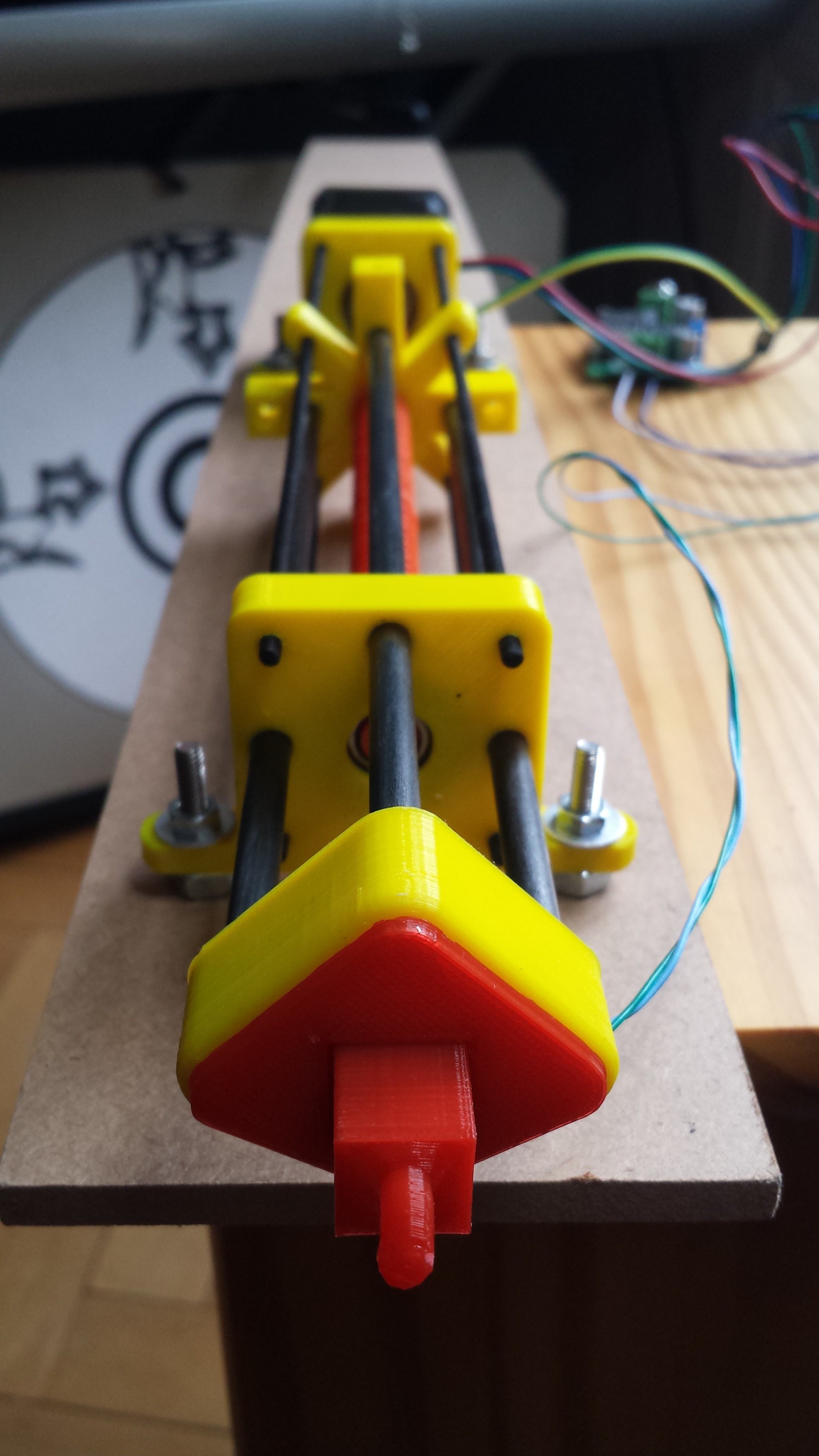
The base unit (yellow) contains a generic 608zz skate bearing to stabilise and allow loading of the lead screw (orange).
Also at the bottom of the base unit you see also the generic tactile switch used as a limit switch (and of course for setting the zero point of the stepper travel).
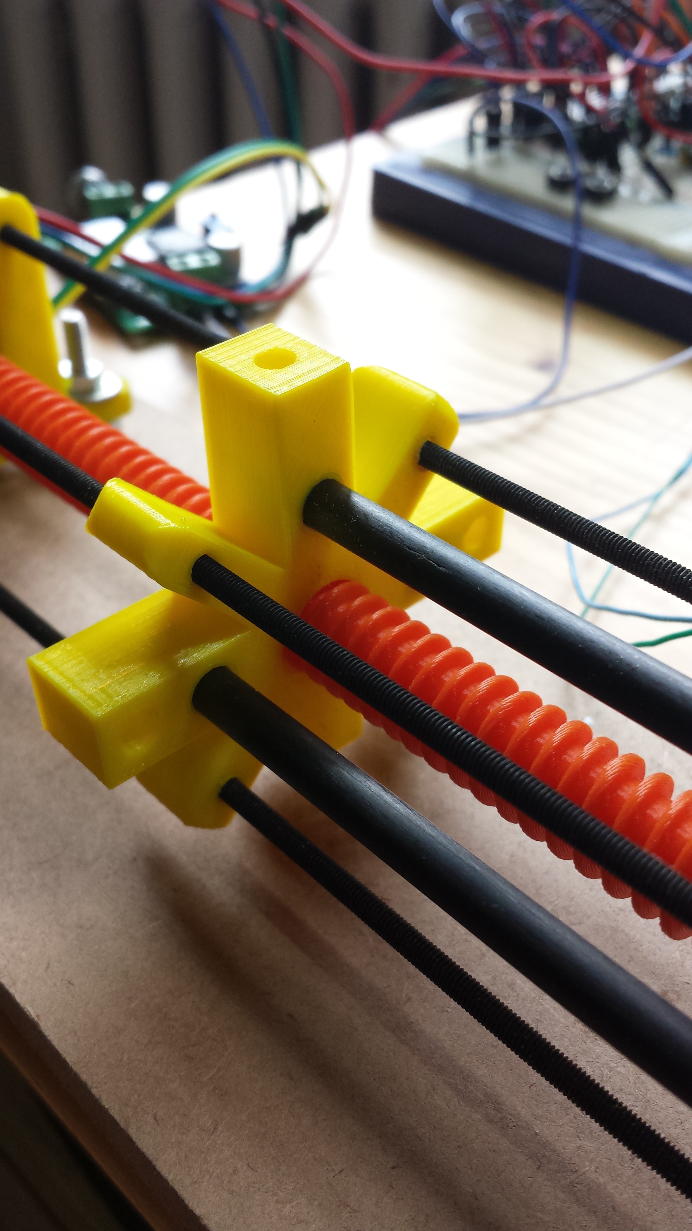
 The mid section is the bottom part of the actuator itself, for multi-purposes its been designed with lots of holes, guides and attachment points.
The actuator is stabilised in 4 different way.
- Clamping holes (above picture).
- Four M3 rods bolted into the Stepper motor itself.
- Three Carbon fibre rods that extend to the end of actuator
- Both the actuator (nut) and end plate (with bearing) are extra thick to route the guide rails.
So altogether its a reasonably stable unit with little backlash.
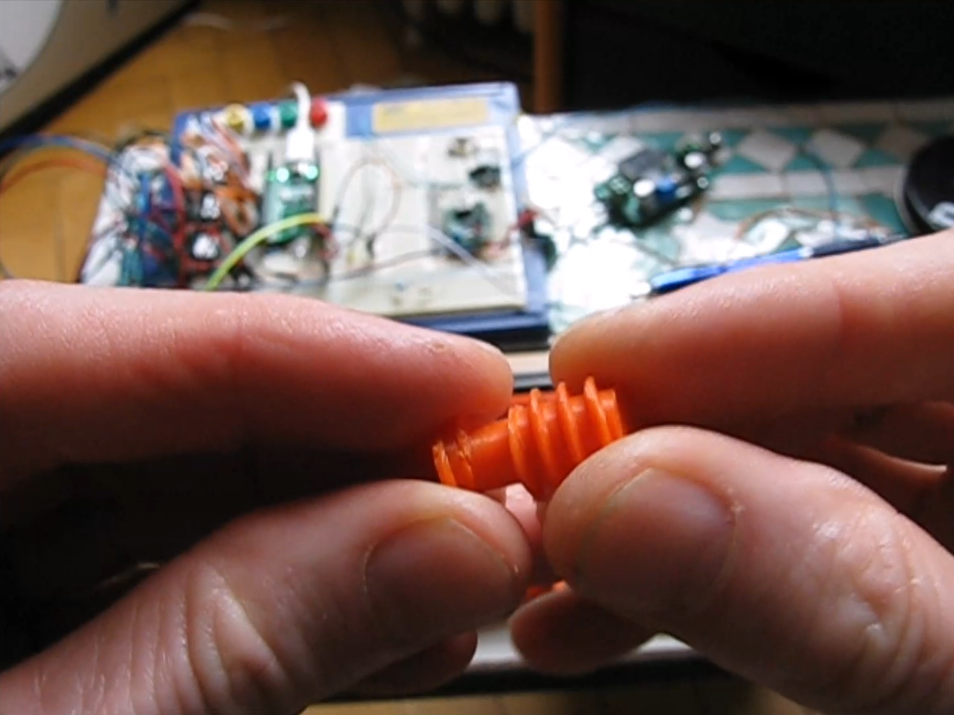
 The lead screw its self is made in segments, so that you can join as many as you like together to get desired stroke length, this actuator has three lead screw segments giving it more that 250mm of travel.
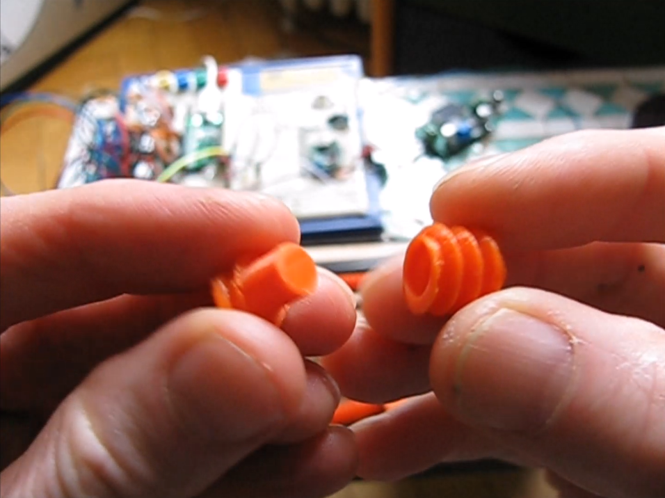 Here is just a quick example of the Plug and play concept, works great.
At the end of the Actuator , mine ends with a load sensor, so that I can control the the dynamic force whilst controlling the actuator.
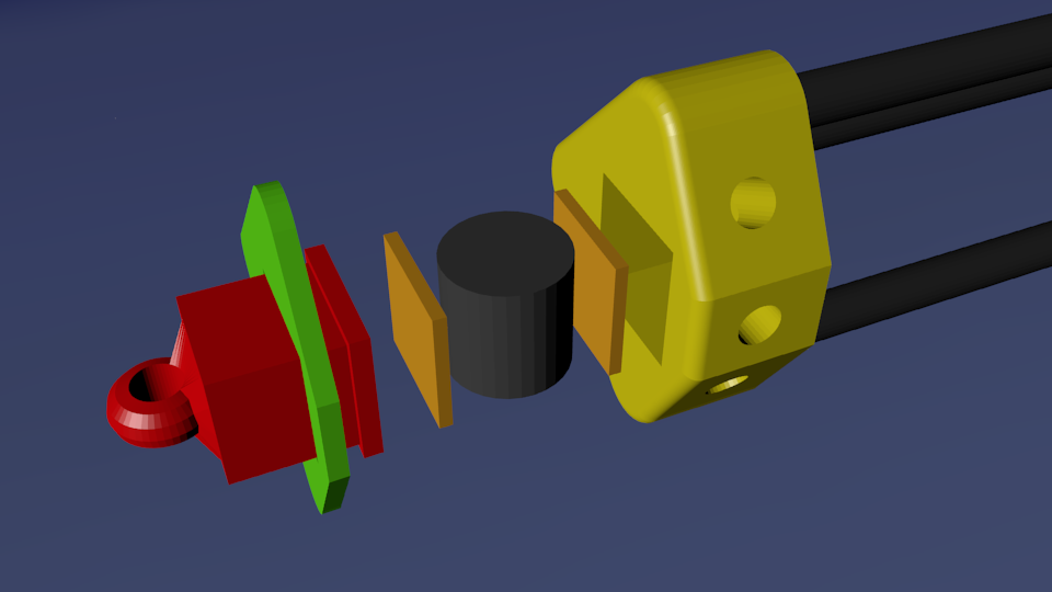
The sensor its self is made from a foam form (ear plug) dipped in conductive ink.
The foam is sand-witched between two copper plates (copper tape actually) , this the slides into the sensor holder and wire fed out of the side.
The plunger (red) basically sit on top and compresses the foam under pressure, the conductive foam alters its resistance under load , which gives the analogue force feedback.
The electronics driving it all comprises of :-
- Nema 17 Stepper motor 47mm
- ESP32 Wroom module, programmed with Arduino IDE
- A4988 Ramps Stepper Motor driver.
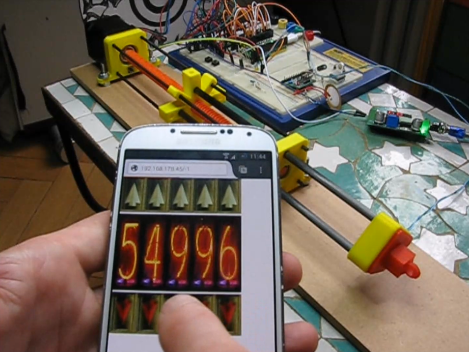
The ESP32 is programmed as Client server, below is a simple test WebGui , it extracts the graphics of my web site.
The elevator up/down buttons are used to step the motor in 1,10,100,1000,10000 steps
The display can either display the Set point or the force of the sensor.

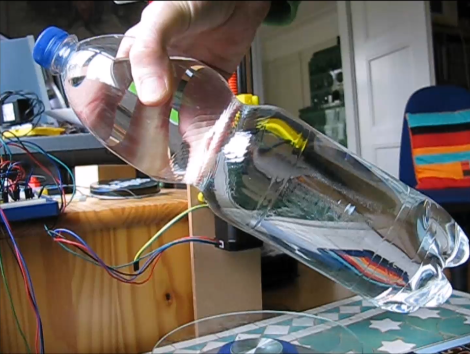
Test subject was a 1.5litre water bottle... weighing in at 1.554 Kg

Lifted the 1.5Kg dead weight easily - It works also at 2Kg (tested), I have not tested it further as two bottles of water are not easy to balance.
very nice design and I was
very nice design and I was first wondering what kind of 3d printer you have to be able to print such a lengthy spindle- but then you resolved that in your movie.
Do you intend to make it a part of InMoov?
Did you try to print the spindle with Iglidur? Would lower friction without having to lubricate.
How happy are you with your self designed pressure sensor? could a spring with a switch do the same or do you get a more detailed pressure reading from the sponge?
Ultimaker - original
All the part where made using an Ultimaker original, the screw part where printed with 0.1mm Z axis 15% infill and most importantly I used a brim for sticking the screw like a limpet to the heated bed(@60°c).
The part are pretty tight and the actuator nut part needs to be run up and down the thread before it runs smooth....
At the moment the screw is running freely without any lubricant, I have used a light grease in the past and even carbon paste might be an option.
I might be possible to print Iglidur style bushes, maybe from nylon filament.
Stepper motors are pretty powerful when geared down , I would like to redesign Inmoovs Biceps with such an actuator, this just might fit. I have also printed a planet gear unit which can be placed in series with the actuator ...meaning a three times gear reduction (so 2kg barrier might be surpassed) whether the screw will take 6kgs is another story though :-)
I am getting good results from the dynamic sensor, the end of the actuator has been designed with a 1cm box hole, this allows other devices (ie. micro switches etc to be shoe horned in ..... or various attachment plates with a 1cm plug.
with Iglidur I meant the
with Iglidur I meant the printable filament from Igus. It can be printed like ABS and is also a bit smelly during printing. What filament did you use for the spindle?