Two is better than one...... (or 4 or 8 etcetcetc).
Following successful experiments with 1 single Time of Flight distance sensor mounted to Stepper, watching the scan process its seems to lend its self to setting the scan to just 180° and mount two sensors back to back to extract the whole 360°...... (or 90° scan with 4 sensors, hope you see where I am going with this :-)
Generally I2C devices come with a fixed address, so doubling up the same I2C animals with the same I2C address is not possible...... unless Slave address's are implemented.
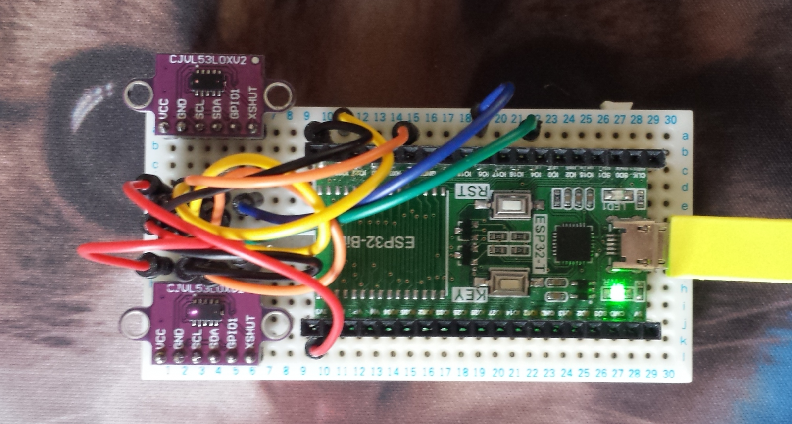
The VL53LOX sensor has a trick up its sleeve ... the "XSHUT" pin (aka... reset pin!).
|
#include <Wire.h> #define XSHUT1 4 #define TOF1_I2Caddress 41 VL53L0X TOF1; void setup()
// the magic part happens here ..... void loop() |
During runtime it is possible to slip any address you wish to each individual sensor.
The TOF comes with a default I2C address of 00101001BIN
The above code is generic so if you have multiple TOF's then the code is easily expanded.....
If you are just using 2 TOF's the simplified code can be used below due to one TOF defaulting to address 41 :-
|
#include <Wire.h> #define XSHUT2 5 // no need to program I2C address of TOF1 as it defaults to 41 anyways \ö/ VL53L0X TOF1; void setup() |

My stepper has a hollow spindle shaft... 5 wires will pass easily through... a 360° rotation would screw the wires up... a 180° rotation would only half screw the wires up... however a 90° rotation would be even better... (i.e. eliminating need for WiFi/BlueTooth OTA data transfer ...FlyByWire becomes an interesting solution again).
Brilliant Gareth ! .. its
Brilliant Gareth ! .. its evolving into a new sensor organ ...
At this point you just need a steper controller & i2c host + 2/4/8/... eyes
what is your stepper degree ? Are you planning to 1/2 step ? I imagine the sampling rate of the sensor is extremely fast, so that sub-degree measurements could be easily made ?
Bugg-eyed monster
I am not 100% on speed yet.... though a single sample acquisition takes (of pdf spec) 35ms
The stepper is a 200 step ... and yes I have wired the microstepping to logic pins ...so step angle can be changed on the fly via software (workio)
Scan strategy is not yet clear.... indeed I had thought of allowing a first scan at high speed (effectively 200 steps over 360°) and then go into micro-stepping when it finds a region of interest.
It all hangs on how much memory I can cram all the scanned data into... time will tell.