Thanks to help of Ray Edgley I publish the 14A continuous (30A peak) analog and digital motor driver. Project is designed mostly for myrobotlab users but it may be used by other peoples. Driver can not be produced and selled
This is not the final version but is fully working with AM and SSM mode.
I think the PCB is the final version, its fully fit to VNH2SP30 shield.
One driver can controll 2 motors 14A each, max Voltage is 16V!.
This Driver have 2 mode of control, AM (analog mode) and SSM (servo signal mode) , in plans is third mode by I2C.
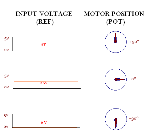
In analog mode AM driver control the motor by 0-5V signal to REF inputs, the POT inputs are for measure the motor position and set it to REF position.
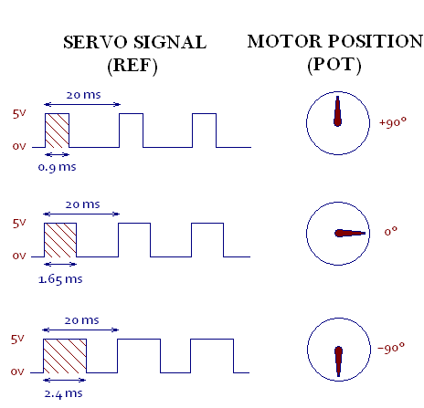
In servo signal mode SSM driver control the motor by the input servo signal from 0.9ms to 2.4ms in 20ms loop connected to REF input. Motor position is controled by POT input like in analog mode.
To chose the mode simply put the jumper in control pins. If the jumper is with +5V the control will be SSM, if the jumper is to gnd then will be AM. The third option will be with no jumper.
Driver has many option like END SWITCH secure, if one of the POT input is connected GND the driver stops on actually position, this work in both of mode.
In SSM mode you may activate/deactivate driver output simply by attach or detach in myrobotlab or unpin POT connection.
Thanks to RAY Edgley Driver have PID regulation thanks to this driver may be set as need, but be carefull changing settings this may results in the driver not being able to control it.
Driver have also Deadband control, this alows the control of positioning accuracy.
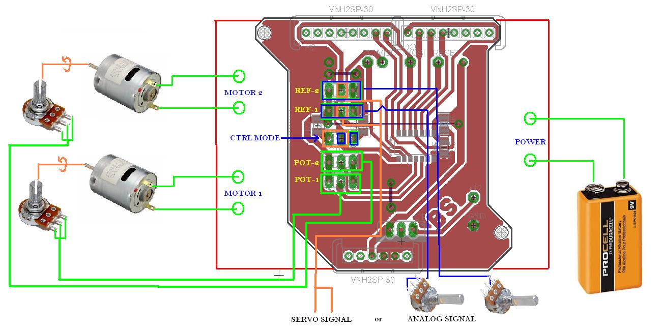
CENNECTIONS EXAMPLE:
Files is in free Cadsoft Eagle
List of parts:
- Attiny44 or Attiny84
- 7805 Voltage regulator
- 2 x 100nF capacitor
- 10K resistor
- 2 x 1K resistor
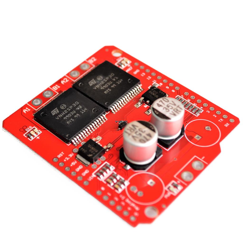
and... VNH2SP30 dual shield for 2 motors controll
https://youtu.be/gkLR8TN4kQ8?list=PLRfNwLnILuI95Y8SjcuXxxm38vTXMN0XA
AM - mode
https://youtu.be/PFGB-MBVAwk?list=PLRfNwLnILuI95Y8SjcuXxxm38vTXMN0XA
SSM - mode
EAGLE FILES <- download
'-----------------------------------------------------------------------------------------'name : servo DIY Driver'copyright : Bartosz Scencelek Bartcam'soft : Ray Edgley & Bartosz Scencelek'micro : attiny44'commercial use : no'-----------------------------------------------------------------------------------------$regfile = "attiny44.dat" ' specify the used micro$crystal = 8000000 ' used crystal frequency'The following is just pinout information'Port Pin Function Used'PB0 2 Output Motor 1 Fwd'PB1 3 Output Motor 1 Rev'PB2 5 OC0A PWM Motor 1'PB3 4 Reset'PA0 13 Output Motor 2 Rev'PA1 12 ADC1 Motor 1 Position'PA2 11 ACD2 Motor 2 Position'PA3 10 Output Motor 2 Fwd'PA4 9 SCL/Ref1 I2C Communications'PA5 8 Input Control Mode'PA6 7 SDA/Ref2 I2C Communications'PA7 6 OC0B PWM Motor 2'############################################' Just a note on the Control Mode'' When set to VCC we will use the PA4 and PA6' as I2C communications'' When set to Gnd We will use the PA4 and PA6' as PWM inputs for Ref1 and Ref2'' When set to 2.5V or ADC 512 we will use PA4 and PA6' as Analog inputs for Ref1 and Ref2'############################################Dim Pot1 As Single 'Current Average position value Motor 1Dim Pot2 As Single 'Current Average position value Motor 2Dim Ref1 As Single 'Motor 1 Target PositionDim Ref2 As Single 'Motor 2 Target PositionDim Refcount1 As WordDim Refcount2 As WordDim Err1 As SingleDim Err2 As SingleDim Integral1 As SingleDim Integral2 As SingleDim Derivative1 As SingleDim Derivative2 As SingleDim Preverr1 As SingleDim Preverr2 As SingleDim Output1 As SingleDim Output2 As SingleDim Kp1 As SingleDim Ki1 As SingleDim Kd1 As SingleDim Kp2 As SingleDim Ki2 As SingleDim Kd2 As SingleDim Deadband1 As Single 'Motor 1 DeadBandDim Deadband2 As Single 'Motor 2 DeadBandDim Filter As Single 'Filtering ValueDim Filter2 As SingleDim Temp2 As SingleDim Temp3 As WordDim Dt As SingleDim Controltype As BitDim Pwm_control As ByteConfig Portb.0 = Output 'Motor1 FwdConfig Portb.1 = Output 'Motor1 RevConfig Portb.2 = Output 'Motor1 PWMConfig Porta.0 = Output 'Motor2 RevConfig Porta.3 = Output 'Motor2 FwdConfig Porta.7 = Output 'Motor2 PWMConfig Porta.5 = Input 'input Mode "Cotrol"Config Porta.2 = InputConfig Porta.1 = InputConfig Adc = Single , Prescaler = 2Config Timer0 = Pwm , Compare_a_pwm = Clear_up , Compare_b_pwm = Clear_up , Prescale = 1Config Timer1 = Timer , Compare_a = Disconnect , Compare_b = Disconnect , Prescale = 8Controltype = Porta.5'****if you want to use only one mode set controltype below****' Controltype = 1' Controltype = 0Enable InterruptsOn Pcint0 Chint SaveOn Oc1a Pwmint SaveIf Controltype = 1 Then 'This section for PWM Input Enable Pcint0 Pcmsk0 = &B01010000 'pin4 and pin6 as int Set Pcie0 Enable Oc1a Start Timer1 Tcnt1 = 0 Pwm_control = 0 Set Pcint4 Set Pcint6End IfOcr0b = 0 'Motor1 PowerOcr0a = 0 'Motor2 Power' the OCR1A (Output Compare Register 1 A) is used to generate an interruput every' 20 mS which is the pulse period of most PWM controlled servos.' Since this controller will be working as a servo driver, we need to use' the same timings.' 20mS periods occure 50 times per second' With a system clock of 8000000 cycles persecond, 160000 cycles will elapse each period.' Timer/Counter 1 can coun up to 65535 before it over runs, so we need to use a prescaler' of at least 2.441 times. This of course does not exist, so the next lowest available' is 8 time. Soo if we take 8000000/8 gives us 1000000. we divide that by our 50 times' per second, we get 20000, which is below the max of 65535, so we set the OCR1A to 20000' if a PWM pulse exceeds the 20 mS, then we will set the ref to the current pos.Ocr1a = 20000 'PWM input TimerReset Portb.0 'Motor1 FwdReset Portb.1 'Motor1 RevReset Porta.0 'Motor2 RevReset Porta.3 'Motor2 FwdStart Timer0 'PWM Output TimerRef1 = 512Ref2 = 512Integral1 = 0Integral2 = 0Kp1 = 1.0 'power force at distanceKi1 = 0.4 'power step in reaction timeKd1 = 0.001 'reaction time (higher faster)Kp2 = 1.5 'power force at distanceKi2 = 0.5 'power step in reaction timeKd2 = 0.02 'reaction time (higher faster)Deadband1 = 10Deadband2 = 10Filter = 5 ' Set the filter to 5 CyclesFilter2 = 6Dt = 0.00173Waitms 200Do'*************** Motor Feed Back with Filtering *************' By taking the existing pot value and multiplying it by Filter' then adding the raw pot value and deviding the total by Filter + 1' We end up with a sudo average taken over filter cycles through the program' The best part of this method of averaging is it is fast and doen't' used much memory, the down side is it can take a long time for the average' to match the raw when the raw is not moving. Temp3 = Getadc(1) Temp2 = Temp3 Pot1 = Pot1 * Filter Pot1 = Pot1 + Temp2 Pot1 = Pot1 / Filter2 Temp3 = Getadc(2) Temp2 = Temp3 Pot2 = Pot2 * Filter Pot2 = Pot2 + Temp2 Pot2 = Pot2 / Filter2'############################################################' Control Method 2 Analog input control.'############################################################ If Controltype = 0 Then ' Analog Input Control Temp3 = Getadc(4) Temp2 = Temp3 Ref1 = Ref1 * Filter Ref1 = Ref1 + Temp2 Ref1 = Ref1 / Filter2 Temp3 = Getadc(6) Temp2 = Temp3 Ref2 = Ref2 * Filter Ref2 = Ref2 + Temp2 Ref2 = Ref2 / Filter2 Else ' PWM input Control If Refcount1 < 19264 And Refcount1 > 17280 Then Temp3 = 19264 - Refcount1 Temp3 = Temp3 / 1.6 Ref1 = Ref1 * Filter Ref1 = Ref1 + Temp3 Ref1 = Ref1 / Filter2 Else Ref1 = Pot1 End If If Refcount2 < 19264 And Refcount2 > 17280 Then Temp3 = 19264 - Refcount2 Temp3 = Temp3 / 1.6 Ref2 = Ref2 * Filter Ref2 = Ref2 + Temp3 Ref2 = Ref2 / Filter2 Else Ref2 = Pot2 End If End If'############################################################' PID Loop to calculate the output value from the Input Error'############################################################ Err1 = Ref1 - Pot1 Temp2 = Err1 * Dt Integral1 = Integral1 + Temp2 Temp2 = Err1 - Preverr1 Temp2 = Preverr1 + Err1 Derivative1 = Temp2 / Dt Derivative1 = Derivative1 * Kd1 Temp2 = Integral1 * Ki1 Output1 = Kp1 * Err1 Output1 = Output1 + Temp2 Output1 = Output1 + Derivative1 Preverr1 = Err1 If Err1 = 0 Then Output1 = 0 'end switch to GND stop If Output1 > 255 Then Output1 = 255 Elseif Output1 < -255 Then Output1 = -255 End If Err2 = Ref2 - Pot2 Temp2 = Err2 * Dt Integral2 = Integral2 + Temp2 Temp2 = Err2 - Preverr2 Derivative2 = Temp2 / Dt Derivative2 = Derivative2 * Kd2 Temp2 = Integral2 * Ki2 Output2 = Kp2 * Err2 Output2 = Output2 + Temp2 Output2 = Output2 + Derivative2 Preverr2 = Err2 If Err2 = 0 Then Output2 = 0 'end switch to GND stop If Output2 > 255 Then Output2 = 255 Elseif Output2 < -255 Then Output2 = -255 End If'############################################################' Drive the Motor Output and PWM signal.'############################################################ If Output1 > Deadband1 Then ' Is the motor to far along Set Portb.0 ' Turn on the Fwd output Reset Porta.0 ' Turn off the Rev output Ocr0a = Output1 ' Set the PWM to Output Else Output1 = Output1 * -1 If Output1 > Deadband1 Then ' Is the motor not far enough along Reset Portb.0 ' Turn off the Fwd output Set Porta.0 ' Turn on the Rev output Ocr0a = Output1 ' Set the PWM to Output Else Reset Portb.0 ' Turn off the Fwd output Reset Porta.0 ' Turn off the Rev output Ocr0a = 0 ' Turn Off the PWM End If End If If Output2 > Deadband2 Then ' Is the motor to far along Set Porta.3 ' Turn on the Fwd output Reset Portb.1 ' Turn off the Rev output Ocr0b = Output2 ' Set the PWM to Output Else Output2 = Output2 * -1 If Output2 > Deadband2 Then ' Is the motor not far enough along Reset Porta.3 ' Turn off the Fwd output Set Portb.1 ' Turn on the Rev output Ocr0b = Output2 ' Set the PWM to Output Else Reset Porta.3 ' Turn off the Fwd output Reset Portb.1 ' Turn off the Rev output Ocr0b = 0 ' Turn Off the PWM End If End IfLoopChint: If Pwm_control = 0 Then If Pina.4 = 0 Then Tcnt1 = 0 Pwm_control = 1 Reset Porta.4 End If Elseif Pwm_control = 1 Then If Pina.4 = 1 Then Refcount1 = Tcnt1 Tcnt1 = 0 Set Porta.6 Pcmsk0 = &B01000000 Pwm_control = 2 End If Elseif Pwm_control = 2 Then If Pina.6 = 0 Then Tcnt1 = 0 Pwm_control = 3 Reset Porta.6 End If Elseif Pwm_control = 3 Then If Pina.6 = 1 Then Refcount2 = Tcnt1 Tcnt1 = 0 Set Porta.4 Pcmsk0 = &B00010000 Pwm_control = 0 End If End IfReturnPwmint: If Pwm_control = 0 Or Pwm_control = 1 Then Pwm_control = 2 Pcmsk0 = &B01000000 Refcount1 = 0 Elseif Pwm_control = 2 Or Pwm_control = 3 Then Pwm_control = 0 Pcmsk0 = &B00010000 Refcount2 = 0 End IfTcnt1 = 0Return
solutions of sterring
first option
second option
and this is what i have now, only for testing manualy all mechanism (soft is for this and need to write it to other solutions) , most importand is the dynamics of motor stering. Manually I check all solutions of motors dynamics. Motors must be fast but with correct acceleration and braking (manually may check all of the solutions)
Bartcam as Discussed
Try this out Bartcam
Hello Bart,
Try out the following code.
it uses over 80% of the Flash memory but does have PID control with a choice of Analog control or PWM input like an RC servo. Output is dual cahnnel PWM.
OK, i modify PCB and check
OK, i modify PCB and check this out. I read all the code and it seems to be Very OK. I am impressed Ray!
Do let me know how it
Do let me know how it goes.
There are ome serious limitations with this chip, and the programming software.
But it will be interesting to know if it works.
Ray
Chip may be changed to other
Chip may be changed to other like atmega or xmega..
Wow Bartcam ! Such a great
Wow Bartcam !
Such a great post with your excellent mobile platform solutions.
Quality work - thanks for posting.
PB3 - is the reset pin of
Thank You Grog, and thank You Ray...
PB3 - is the reset pin of microcontroller (if I swich off this i can not program it)
ok i try to project new PCB for those, I must think about how to comunicate by I2C without any breaks in ADC, on int, we must do some sub funcion where we get signals from I2C.
We have one pin free, this may be used for some endstop switch, better will be to use two pins , one for each motor..
problem with filtering
There is problem with filtering in program, if I use
output1=ref1-pot1
without this filtering:
with this filtering all works in only one direction, I belive there is some small mistake in calculations. I try to find this ;/
all it's working in analog mode, I don't checked PWM and I2C mode yet.
Sorry no I2C mode ... yet!
Ok, i find one problem:
Derivative1 = Derivative1 * Kd1
Derivative1 will be always =0 because Kd1 is =0
hmmm filter is working in excel maybe is something with variables in bascom
errors in simulation
that I am think about in simulations in bascom of filtering is many errors.
I cutted the code and do a small of it to simulation only:
Is it the interrupts?
Is it possible the error is comming from an external source such as the two timer interrupts?
There are quite a number of interrupts on the tiny84, i used one for the two pwm outputs, and one is usec for the pwm input timing!
At last work on analog mode
At last work on analog mode with PID :)
but, no live with PWM mode, I connected normal servo to check signal from the arduino and normal servo its working , an these same pin DIY SERV DRV not work. I thin there is something with INT.
.
.
.
.
OK i found there is no ENABLE PCINT(X)
SET PCINT(x) - what for ? I think it is not neccecery.
Tommorow is next day of checking :P
Possible correction
Hello Bartca,
I noticed that you are running with higher counts than was origonally calculated, not sure where I got it wrong,
In one of the comments you made you mentioned having to restric the range due to instability, There is a setting that may not have been taken into account.
Up the the setup section, we set OCR1A to 20000, with the real world results we are seeing this may be should have been closer to 40000.
Just a thought
The OCR1A is used to trigger the interrupt for loss of signal in what you called SSM mode (I called it PWM mode, but your naming will lead to less confusion so I will match your naming)
Ray
Who was able to run this
Who was able to run this driver? SSM mode does not work for me