TaskHandle_t Task1;
TaskHandle_t Task2;
 #include <Wire.h>
 #include <DS3231.h>
 #include <analogWrite.h>
 #define PARALLEL_0  14  //12 create a parallel bus using GPIO 12,13,14,15 i.e. consecutive pins
 DS3231 Clock;
 byte Year;byte Month;byte Date;byte DoW;byte Hour;byte Minute;byte Second;byte Neon;bool Century=false;bool h12;bool PM;
int pausey ; int copperbuttons ; int oldsecond;int countdown;
int tube=0;int digit=0;int tubebar[4];
byte touch1;byte touch2;byte touch3;byte touch4;byte touch5;byte touch6;byte touch7;byte touch8;
int settimeloop;
void setup() {
 ledcSetup(2,1E5,12);

  for (int i = 0; i < 3; i++) {
    pinMode(PARALLEL_0 + i, INPUT); //setp up as inputs ....however can be used as outputs ...see below.
  }
  parallel_set_outputs();

   //create a task that will be executed in the Task1code() function, with priority 1 and executed on core 0
  xTaskCreatePinnedToCore(
                    Task1code,   /* Task function. */
                    "Task1",     /* name of task. */
                    10000,       /* Stack size of task */
                    NULL,        /* parameter of the task */
                    1,           /* priority of the task */
                    &Task1,      /* Task handle to keep track of created task */
                    0);          /* pin task to core 0 */

  //create a task that will be executed in the Task2code() function, with priority 1 and executed on core 1
  xTaskCreatePinnedToCore(
                    Task2code,   /* Task function. */
                    "Task2",     /* name of task. */
                    10000,       /* Stack size of task */
                    NULL,        /* parameter of the task */
                    1,           /* priority of the task */
                    &Task2,      /* Task handle to keep track of created task */
                    1);          /* pin task to core 1 */

    Serial.begin(57600);
    Wire.begin();

   pinMode(14, OUTPUT);  pinMode(15, OUTPUT); pinMode(16, OUTPUT);  pinMode(17, OUTPUT); // bcd
  pinMode(18, OUTPUT);  pinMode(19, OUTPUT);  pinMode(25, OUTPUT);  pinMode(26, OUTPUT);  // Nixie tube

  pinMode(32, OUTPUT); pinMode(33, OUTPUT);// seconds neon
 }
void loop() {
      touch5= touchRead(4); delay(80); touch6=touchRead(4);  delay(80);
      touch7= touchRead(27); delay(80); touch8=touchRead(27);  delay(80);
      touch1= touchRead(12); delay(80); touch2=touchRead(12);  delay(80);
      touch3= touchRead(13); delay(80); touch4=touchRead(13); delay(80);

     copperbuttons=((touch5<40)&(touch6<40))*8 + ((touch7<40)&(touch8<40))*4 + ((touch3<40)&(touch4<40))*2 + ((touch1<40)&(touch2<40))*1 ;
switch (copperbuttons){
     case 3: Serial.println("Right pair");delay(100); break ;
     case 6: Serial.println("Middle Pair");delay(100); alarm();break ;
     case 12: Serial.println("Left pair");delay(100); break ;
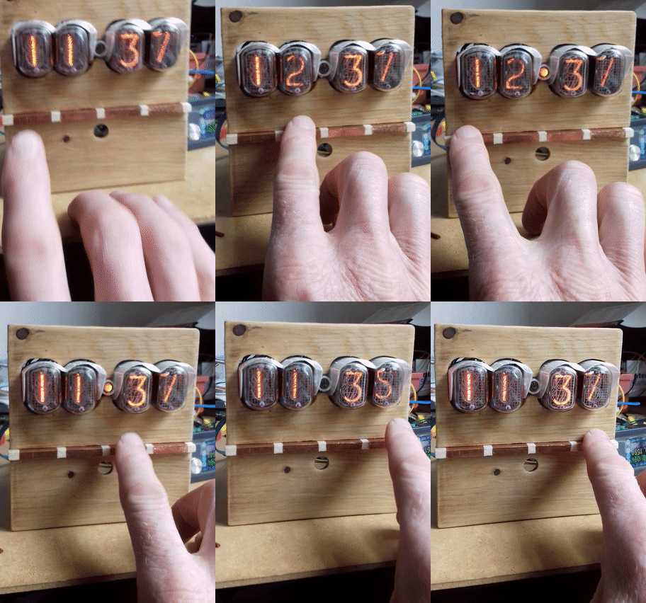
     case 15: Serial.println("Set Time");delay(100); countdown=10;oldsecond=Clock.getSecond(), DEC;set_time(); break ;
}

}
void tubedigit (int i)
{
 Hour=Clock.getHour(h12, PM), DEC;
 Minute=Clock.getMinute(), DEC;
 Second=Clock.getSecond(), DEC;
 Neon=Second>>1;Neon=Neon<<1;

 tubebar[0]=Minute-((Minute/10)*10);
 tubebar[1]=Minute/10;
 tubebar[2]=Hour-((Hour/10)*10);
 tubebar[3]=Hour/10;
  for ( i=0; i <=3; i++){
parallel_write( tubebar[i]); //output gpio 12,13,14,15 as a bitwise operation

int j=i;
if (j==0) {digitalWrite(18, LOW); digitalWrite(19, LOW);  digitalWrite(25, LOW); digitalWrite(26, HIGH);}
if (j==1) {digitalWrite(18, LOW); digitalWrite(19, LOW);  digitalWrite(25, HIGH); digitalWrite(26, LOW);}
if (j==2) {digitalWrite(18, LOW); digitalWrite(19, HIGH);  digitalWrite(25, LOW); digitalWrite(26, LOW);}
if (j==3) {digitalWrite(18, HIGH); digitalWrite(19, LOW);  digitalWrite(25, LOW); digitalWrite(26, LOW);}
delay(5);
}
}

//Task1code: Call tubedigit update
void Task1code( void * pvParameters ){

  for(;;){
   tubedigit(0);
  }
}

//Task2code: blink Neon seconds indicator
void Task2code( void * pvParameters ){

 for(;;){
  if (Second==Neon) {analogWrite(32,20);} else {analogWrite(32, 0);} // dimmable pwm
}
}

void parallel_set_outputs(void) {
  REG_WRITE(GPIO_ENABLE_W1TS_REG, 0xFF << PARALLEL_0);
}
void parallel_write(uint8_t value) {
  uint32_t output =
    (REG_READ(GPIO_OUT_REG) & ~(0xFF << PARALLEL_0)) | (((uint32_t)value) << PARALLEL_0);

  REG_WRITE(GPIO_OUT_REG, output);
}
void set_time (){
uint32_t period = 1 * 20000L;

for( uint32_t tStart = millis();  (millis()-tStart) < period;  ){
    touch5= touchRead(4); delay(80); touch6=touchRead(4);  delay(80);
    touch7= touchRead(27); delay(80); touch8=touchRead(27);  delay(80);
    touch1= touchRead(12); delay(80); touch2=touchRead(12);  delay(80);
    touch3= touchRead(13); delay(80); touch4=touchRead(13); delay(80);

    copperbuttons=((touch5<50)&(touch6<50))*8 + ((touch7<50)&(touch8<50))*4 + ((touch3<50)&(touch4<50))*2 + ((touch1<50)&(touch2<50))*1 ;
switch (copperbuttons){
     case 1: Minute++;Clock.setMinute(Minute); delay(50);  break ;
     case 2: Minute--;Clock.setMinute(Minute); delay(50);  break ;
     case 4: Hour++;Clock.setHour(Hour); delay(50);  break ;
     case 8: Hour--;Clock.setHour(Hour); delay(50);  break ;
 }
delay(100);
}

}
void minute10 (){
uint32_t period2 = 1 * 60000L;
for( uint32_t tStart2 = millis();  (millis()-tStart2) < period2;  ){
}
}
void alarm(){
  ledcAttachPin(33, 2);
   for (int ii=000; ii <= 5000; ii=ii+66){
       ledcWriteTone(2,ii);
      delay(8);
   }
  for (int ii=5000; ii >= 000; ii=ii-33){
       ledcWriteTone(2,ii);
      delay(8);
     }
     ledcDetachPin(33);
}
|


Great build Gareth ! I've
Great build Gareth !
I've never used "Numeric Indicator eXperimental No. 1" tubes ...
The high tension certainly looks like a challenge to work through.
What is the voltage ?
Circa - 170 Volts - on a good day
The flying inductor arrangement runs at circa 31 Khz (via astable ne555 timer) and produces choppy 170 DC Volts....sofar I have escaped contact with it.... 3D printed guards are helping..
As the nixie tubes do not require much current (circa 1mA) this simple arrangement works well.
On the nixie Long indicator tubes I am experimenting with an 08M2 picaxe chip to generate the 31 Khz signal using pwm codes... it works fine. (I went the 08M2 route after my experiments with using the second core of the ESP32 (i.e. simple output pin oscillator) killed 2 of my esp'2 (more cost effective to blue smoke 08M's).
(yes I have 3 to enjoy :-)