Hi guys! :)
I have a project that uses arduino and pan/tilt servos to track a desired color. With the use of a camera and myrobotlab, this project slowly come to life. I and with the help of GroG, are working on it to make it possible. However, it's not yet done and the project is still under progress. Here's some of the highlights of the project. Comments and Suggestions will be greatly appreciated :)
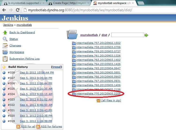
First, you need to download MRL:
-you can download MRL at this link. Be sure to pick the latest build ( at this time of writing, the latest is ver.770) Here's the link: http://myrobotlab.dyndns.org:8080/job/myrobotlab/ws/myrobotlab/dist/
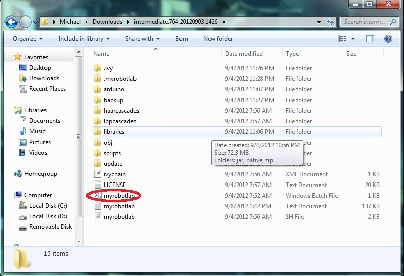
Next is you have to extract and open the folder and open myrobotlab.bat file:
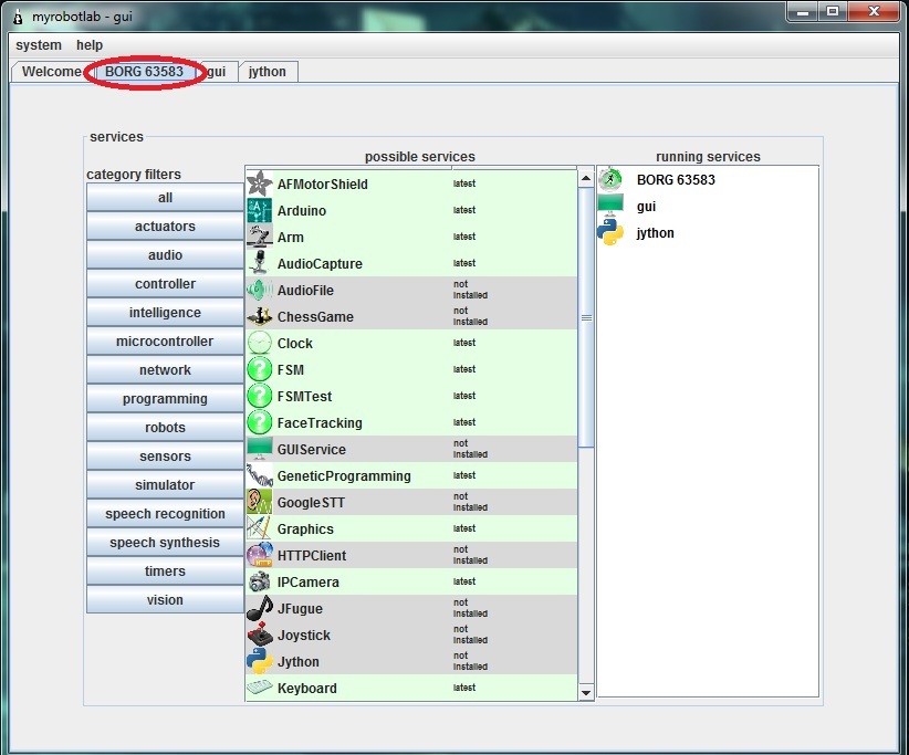
After a while it should run like this:
Notice the BORG tab selected :)
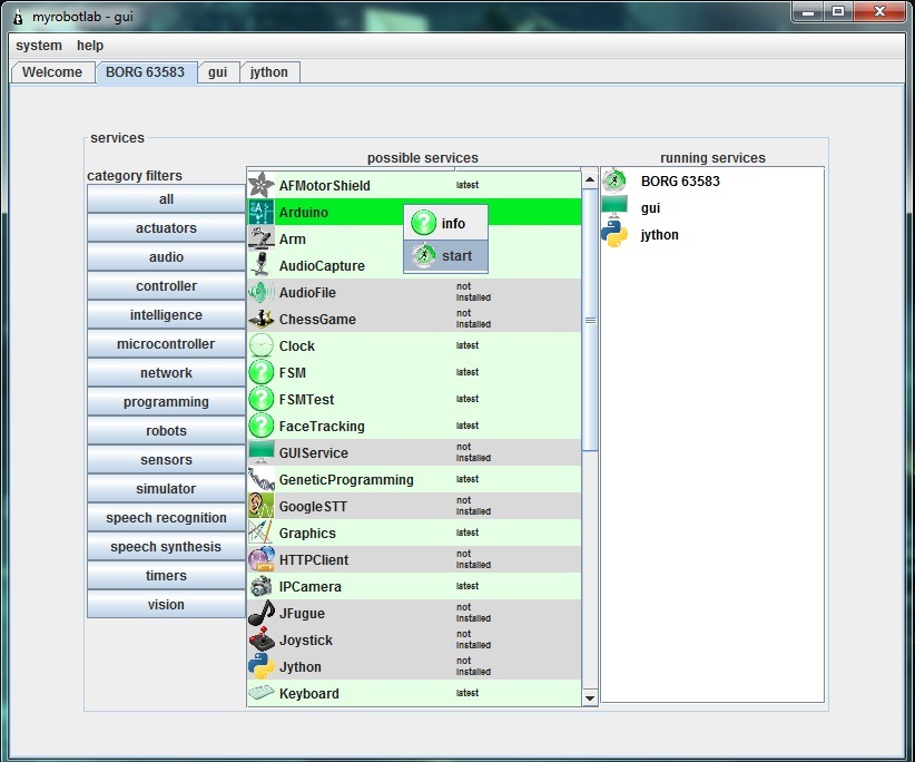
Next is you should download the arduino service. Just right click the arduino service and click install. The same procedure applies to the OpenCV service
NOTE: Some anti-virus programs don't permit downloading the services. For me, I turned of my firewall and it worked.
Here's a pic (disregard the start under the info. It should be install because I already downloaded the service)
After downloading the Arduino and OpenCV service, Run OpenCV service by right clicking and choosing start. Then, name your service. Here I called it OpenCV. Click the OpenCV tab and scroll down the filters and select the PyramidDown filter to avoid the video booming up in your screen XD. and select the camera button then press capture. Normally the stop button is capture. :
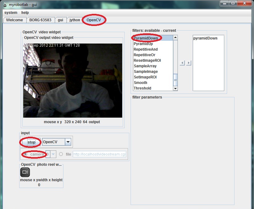
Next is select the InRange filter to select the color you want to be tracked. Click the Inrange filter. Play with the values until the desired color will become white.
Pic:

Color tracking is a bit sensitive. Sometimes you should be consistent with the color ( due to poor lighting and etc. that affects the color consistency) so you'll have to update those values sometimes to get an accurate output.
Now, if you are all set, Remember the values in InRange filter. Like this from the picture above:
Parameters Min Max
HUE 3 33
SATURATION 87 256
VALUE 151 256
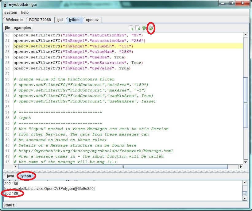
If you are done taking down the values select the jython tab and copy these codes. You NEED to replace the values in "change values of the InRange filter with your own values that you took down down a while ago.
Now if you are done copying. Hit execute button( the button with a gear :D) . Notice in the pic below the jython console is printing x,y coordinates that later will be sent to arduino.
Now, start arduino service and follow these steps:
1- click tools and choose board then select the arduino model you have
2- click again tools and choose Serial Device then select the proper COM port the arduino uses(at this time your arduino should be connected in your computer)
3- click the compile (check) button. Wait for it to finish compiling (when you see a "done" in the console)
4- click the upload button and again wait for it to finish
5- click the connect button. Wait for the "good times"
Test the connection by clicking the pins tab and selecting some analog pins to active. Put some wires or sensors (potentiometers, etc.) to the analog pins. Then, select oscope tab to view some values sent to the myrobotlab.
Stay tuned :)
Yay !
Umm.. I don't understand what you mean?
Please change the servo script cause it's still in the loop <-- To what, do you mean to track ?
We need 2 PIDs to map... I'll start that script...
So when you run the whole script you should see the following behavior :
OpenCV -> starting, creating filters, setting values -> then publishing the center coordinates of an object
Arduino -> starting, connecting to the serial port, starting a analog pin (Oscope readout)
2 x Servos -> starting, attaching themselves to the Arduino on the correct pins - moving in a loop for a while
Are we good on all of these?
Did the upload to the Arduino work from MRL ?
Next will be to start 2 PIDs to do remapping off coordinates - they will listen to the OpenCV X coordinate and translate to commands on the pan servo...
The other will listen to Y coordinates and translate to the Tilt servo..
Nevermind this line: please
Nevermind this line: please change the servo script...... XD
Anyways, I uploaded successfully in the arduino in MRL eventhough it takes too long :) Oscope is running a trace too.
Yes, we can now start the final script :D
Yes,getting closer to the
Yes,
getting closer to the "final", I've added 2 PID services (one X and one Y) - havent checked it in yet...
Do you have a usb joystick of some sort? I'd like to test the tracking & PID with a joystick before feeding it OpenCV data...
It looks like the original joystick service isn't 64 bit compatible, but I have already found another one which is... got to re-write the Joytick service too ...
Yes I do have but it's a usb
Yes I do have but it's a usb steering wheel. Will it work?
Pan and Tilt need 2 axis of
Pan and Tilt need 2 axis of input ... don't know how that could be done with a steering wheel ;)
The new gamepad library
The new gamepad library interface is completely different from the one I was previously using...
This will take a little while..
the usb gamepad will only be
the usb gamepad will only be used for testing right?
BTW, If the gamepad lib/service is accomplished, can we use that to control the robot for wireless applications?
"the usb gamepad will only be
"the usb gamepad will only be used for testing right?" <- correct, however, it would be easy enough to make it so you can "switch" to manual control from OpenCV tracking, with a push of a button.
"BTW, If the gamepad lib/service is accomplished, can we use that to control the robot for wireless applications?" <- yes, you have the right idea - Once a service is added to a system, its messages can be used to affect any other service... So it can control Servo's, Motors, etc... You could even have it control OpenCV filters .. for example pressing different buttons could change the filter configuration, and switch from Color Tracking to Motion tracking...
Sounds exciting! So, it
Sounds exciting!
So, it looks like I have a next project after this color tracking isn't? XDD
Maybe we have issues on rxtx
Maybe we have issues on rxtx that hinders us to communicate with the arduino isn't it? Anyways, I've sent you another logfile. And I'm already patched up with ver.786 bleeding edge.
Is there any micro servos like the ones that I use (Tower pro SG90) laying around in your house?
Maybe we can do this together by making a clone of the servos shield. You just need a 4017 decade counter (I'm using CD4017 here in my shield) connect CLK to pin 6 and RST to pin7.
Here's a pinout for cd4017: http://www.google.com.ph/imgres?hl=en&sa=X&biw=1366&bih=667&tbm=isch&prmd=imvns&tbnid=Ch1w95cc_NAQJM:&imgrefurl=http://www.circuitstoday.com/dancing-light&docid=Aw3WHxuJyM4HVM&imgurl=http://www.circuitstoday.com/wp-content/uploads/2008/08/cd-4017-_pinout.JPG&w=407&h=326&ei=qqNQUKWuLPDvmAXCyYHQDg&zoom=1&iact=rc&dur=414&sig=104450090581769985932&page=1&tbnh=147&tbnw=183&start=0&ndsp=18&ved=1t:429,r:5,s:0,i:85&tx=87&ty=13
And here's the link of the servoshield(not mine) download the eagle files for reference. Be Sure to just use the cd4017 that connects to pins 6-7 on the eagle pcb.
:http://www.renbotics.com/products/servoshield.php
Thanks for the info, Funny, I
Thanks for the info,
Funny, I have already started to put together a pan / tilt kit with 2 servos.
It will take me too long to make a shield, but thanks for the info.
I'll be working on a Adafruit Motor Shield - but the interface to the Servos is different. It uses the Servo libraries which come from Arduino.
Is the pan/tilt kit of yours
Is the pan/tilt kit of yours now working? :)
"For me, the best step for
"For me, the best step for now is to verify Aceduino Shield service runs successfully. In order to that, can we try to use the scrollbar/trackbar in the service to position the desired servo?" <- Can't do this yet, the Aceduino uses its own library and own API which is different from a typical Arduino Servo - We are trying to verify at a lower level (Programming level) that the Aceduino Shield can be controlled correctly by the Arduino. After we do that we can standardize the Aceduino Service to use a "standard" Servo API and then you should be able to attach Servo's to it.
Just so you know: The "I
Just so you know:
Did you download the zip (which is good), unzp, but not "install" the Arduino service, before you ran the script ?
Joystick service done....
Or at least "done enough". And the RXTX libraries have been updated with CreateLab's versions. Unfortunately, create lab's version does not take out the large pause when searching for serial ports on Windows 64 bit os's. The Arduino IDE suffers from this too, as you'll possibly notice when starting the Arduino IDE (the pause is not for graphics, but it's searching for COM ports at the time) - And the Arduino IDE searches for COM ports every time you press the "tools" menu.
Back to the Joystick, service :
I replaced old libraries with new Sun Dev libraries...
I created a Pan / Tilt kit script - it's under Jython->examples->basic->panTilt.py
the values are catered to my system...
I have also found out that Servos are increadibly noisy (electronically) .. so much so they mess with communication and other electronic values on the board...
I'll have a vid & pictures soon...
I'm going to start the
I'm going to start the tracking script now.
Your tracking is only as good as the weakest link... And my weakest link is between the arduino & the Servos (because of servo noise)
Do I have to download the
Do I have to download the latest bleeding edge (zip) to get the new Joystick service or I'll just have to update MRL?
BTW: Nice stop and execute buttons on jython console :))
Hi Michael, When the
Hi Michael,
When the repository changes, it's typically safer to download the zip and re-install the services. In the future this might not be necessary.. but at the moment it is.
I need to finish out some form of Joystick GUI - one which allows you to select the input device - (Joystick, Gamepad, Steering Wheel) - and allows the output to be remapped to value ranges which you find useful.
For example :
0 - 180 for typcial Arduino Servo
-1.0 - 1.0 for raw values
0.0 - 1.0 for positive real range
I'd be curious if your steering wheel is read ad a gamepad - I suspect that it is.
Thanks for the feedback on the buttons, I appreciate any ideas to make MRL more "usable"
Nevermind the steering wheel
Nevermind the steering wheel XD
I'll buy a gamepad tomorrow to suit the pan/tilt kit (steering wheel looks pretty awkward XD)
I was thinking we might not
I was thinking we might not need PID to complete this if you want to map the values with a constant amount.
Let's try to out...
A servo has a range of 0 - 180, roughly 1 increment = 1 degree...
If you use a different servo library you may have a different range e.g. the ACEduino has 500 - 2500, but you can figure out what the timing value corresponds to a degree.
We want a point in the display to be mapped to a servo position location - I think you were saying this all along :D
So you just need to figure out the degree value of a pixel location. This depends on you specific camer, it's the "field of view" and is typically reported as - FOV - 60 degrees...
Since I could not find this spec for my webcam, I calculated it this way (http://myrobotlab.org/node/48)
So I have the range
OpenCV point x = 0 to 320 pixels with a camera which has 57 degrees field of view
320/57 = 5.6 pixels per degree
So for every 5.6 pixels the target is off center we want to move 1 increment of the servo..
Make sense ?
Yes, it does make sense. The
Yes, it does make sense.
The idea somehow or almost alike with my Processing script. I tried some tutorials in the net and I found a face tracking tutorial. The idea is pretty much the same as what you said. It tracks a face by adding (if the face is on the right side) 1 or 2 degrees to the right. I've tried it on my aceduino shield and it successfully ran.
I'll post the Processing code and Arduino code. It might help :))
//////////////////////////////////////////////////////////////Processing////////////////////////////////////////////////////////////////////
Thanks for that... It's good
Thanks for that...
It's good to have other input..
I have not tried it, but the code there does have something I was thinking of avoiding.
When it finds a target it increments but some stepSize (in this case stepSize=1) .. so it moves + or - 1 depending on direction. This does not account for the distance the target is from the center. If the target is very close or near the edge of the field of view, the servos are given directions to move + or - 1. I think it would be nice to estimate the amount - and jump to it in one command..
The code I've done so far is accessable through the bleeding edge update - right now its only the X axis - and its trying to move the servo in absolute location (versus incrementally) . It needs more work, but its a start..
Okay, I'll download now the
Okay, I'll download now the latest bleeding edge build.
Is the code your'e referring is the color tracking script?
Yes,I checked it in with my
Yes,
I checked it in with my config set - you'll have to switch it to yours...
this line to
configType = 'GroG'
changed to
configType = 'michael'
GROG The SCRIPT WORKED! XD
The script's finally working GroG!
I think we can now move on to adding the tilt servo in tracking the object :))
I'll post a vid or maybe a photo soon :)
Thanks!
WhooHoo ! Awesome.. I'm
WhooHoo !
Awesome.. I'm painting stuff today, but tonight I should be able to update it ..
Right On ! (Post a video - I wanna see if your Servos are as noisy as mine)
I added tilt, although didn't
I added tilt, although didn't test much... I'll do more testing later..
Your servos may be inverted to mine so you may need to change the
tilt.moveTo(90 + yAvg/sampleCount) to
tilt.moveTo(90 - yAvg/sampleCount)
you might wan to experiment with the
if (sampleCount > 10): and change 10 to a lower value if your servos & arduino can handle it....
Post some pictures or video when you get a chance..
I will probably get more of a controlled lighting place and see what colors my camera isolates best then do a video - after doing that I'll change to stepper motors & a stepper shield ... considering the problems I've had with servos :P
I think a stepper driven pan / tilt kit might be pretty smooth in comparison.. we'll see..
Fixed a long time bug.. where
Fixed a long time bug.. where filters set programmatically would not populate the GUI - now when a filter is added or removed programmatically, the event is published, and in this case the GUI displays the filter's name. Still have an outstanding bug where filter's data does not display, when it is set programmatically.. And the camera / capture info is not correct - when set in a program
Evil Servos !
Experimenting with the new script... I can see the OpenCV data overwelming my servos. If the noisy servos get too many commands, and too many changes of direction, too quickly, the kill the communication between the computer and the Arduino...
Evil Servos !!!
HAHAHA XD I hope the servos
HAHAHA XD
I hope the servos will cooperate later :D
Do you have now a script on
Do you have now a script on contolling servos with a joystick via MRL.
BTW, I'll try now the pan color tracking. Been busy this past days :))
Here's some info on the
Here's some info on the Joystick Michael - http://myrobotlab.org/service/Joystick