When i built my robot, i liked the idea of an articulating stomach designed by Bob Houston, found as thingiverse thing:1409964.
Bob made a very nice design, but I never felt at ease with using just the 180 degree turn servos and the plastic spindles. They have a rather course pitch and can cause the robot to lean at random , for example when moving an arm.
The main pivot is a 3D printed (duh, what else) ball and socket. This socket is of a clam shell design, as in 2 printed halfs, the tops of the socket halfs are held together with two 3mm screws. Through the center of the ball and socket, in the horizontal direction, a pin constrains rotation in the horizontal plane. In short, the pin only allows, forward, backward and side to side motion. This pin originally is also 3D printed and recently snapped.
After some head scratching and looking at how much stress a mishap could place on this socket, I decided to design a brace around the outsidde of the socket that would capture a 5mm steel pin. This should sufficiently strengthen this area
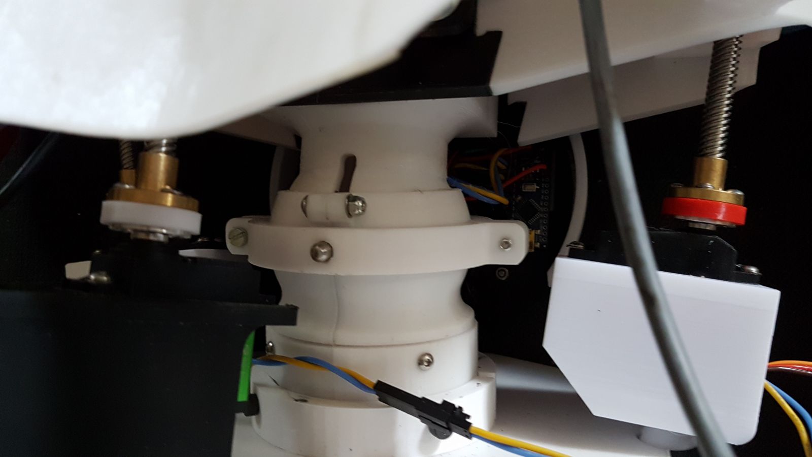
The next part to address were the servo/spindle combinations used. I wanted a stronger spindle so opted for acme threaded rods TR8x8, as these were the coursest threads i could easily source.
I found some files on thinghiverse under: MEGA_Servo_Drive_Piston_for_InMoov_Linear_Actuator, which provided the balls with cut-outs for the side rods. There was some slop between the ball and the pivoting sockets, so I printed the balls at 103% which ended up giving a nice fit. This took care of the side to side motion.
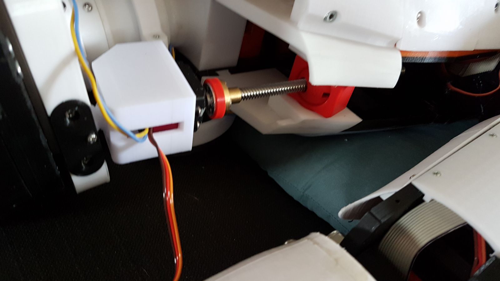
The next problem to tackle was front to back motion. I had recently already reprinted the parts for bob houston's design, I did not like the servos sticking out in the back so turned them 90 degree so they are more in line with the curve in the back. I did not want to reprint the upper block so decided to design an adapter from the course plastic thread to the TR8x8 threaded nut.
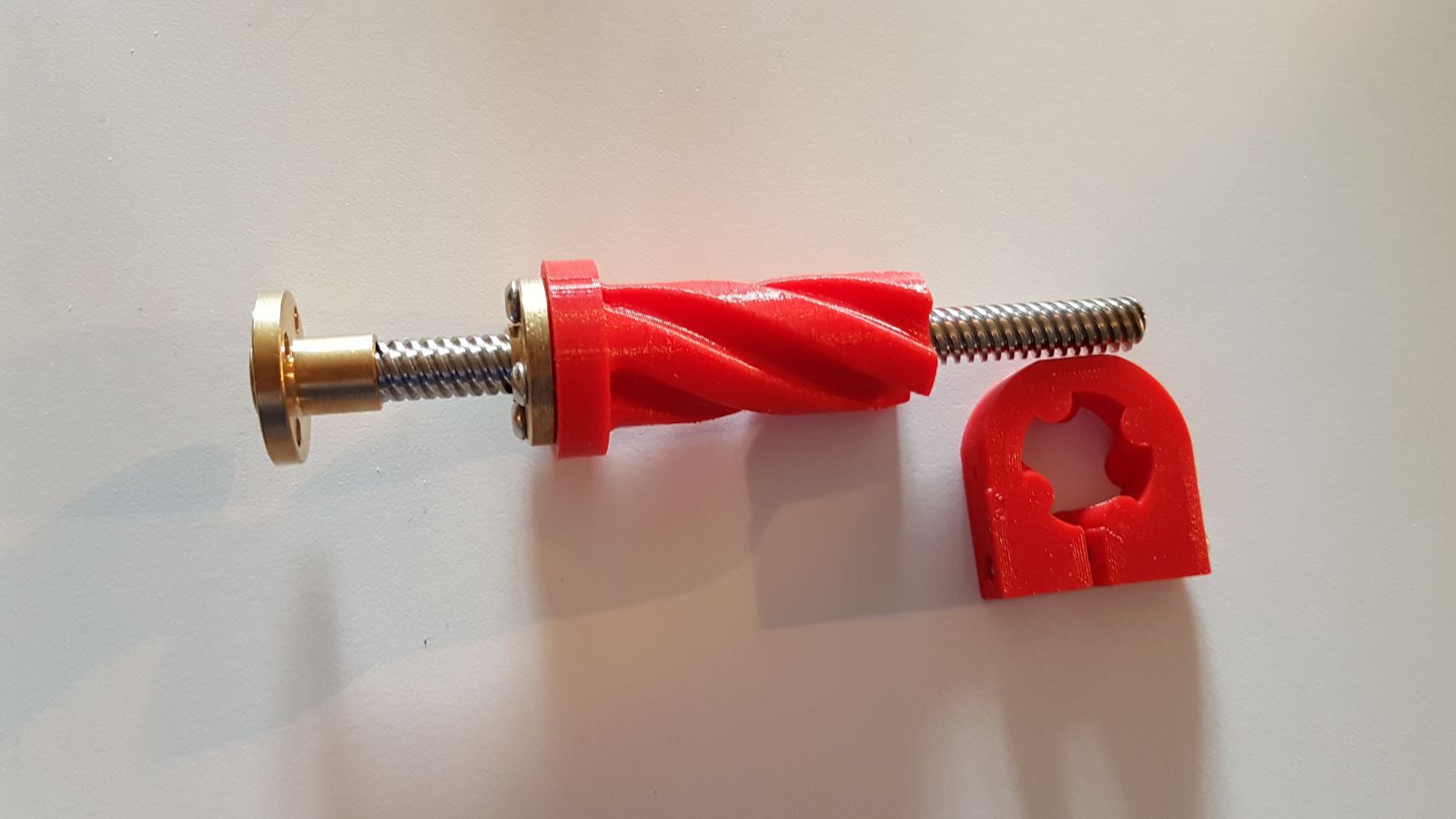
these fit nicely in the upper block attached to the back of the robot. At first I thought I would glue these in, but decided to just put a clamp on the top to make them removable.
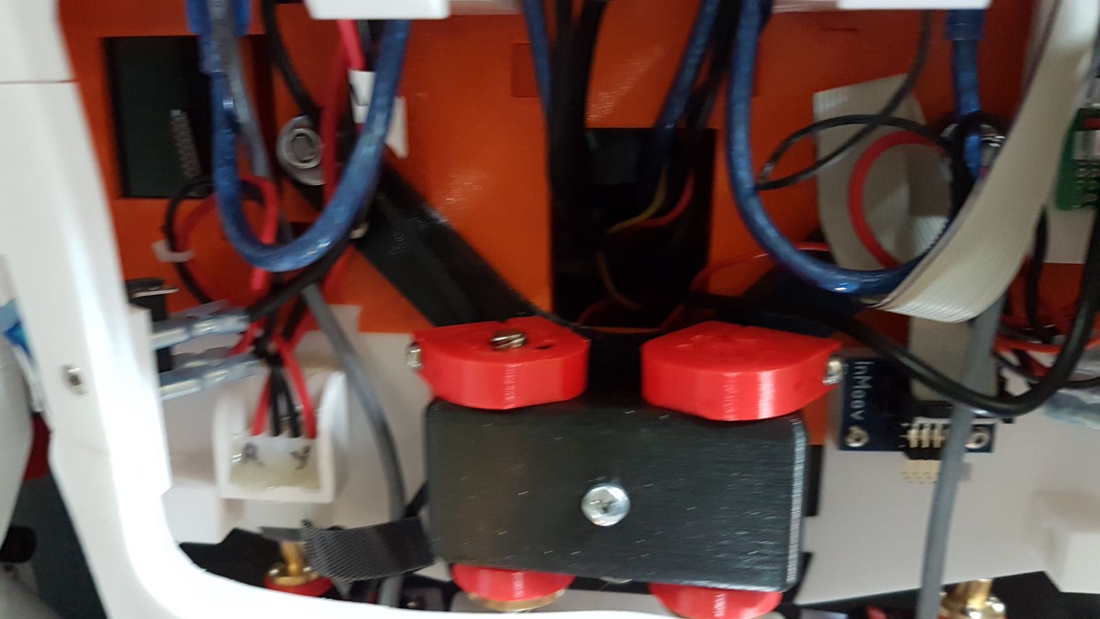
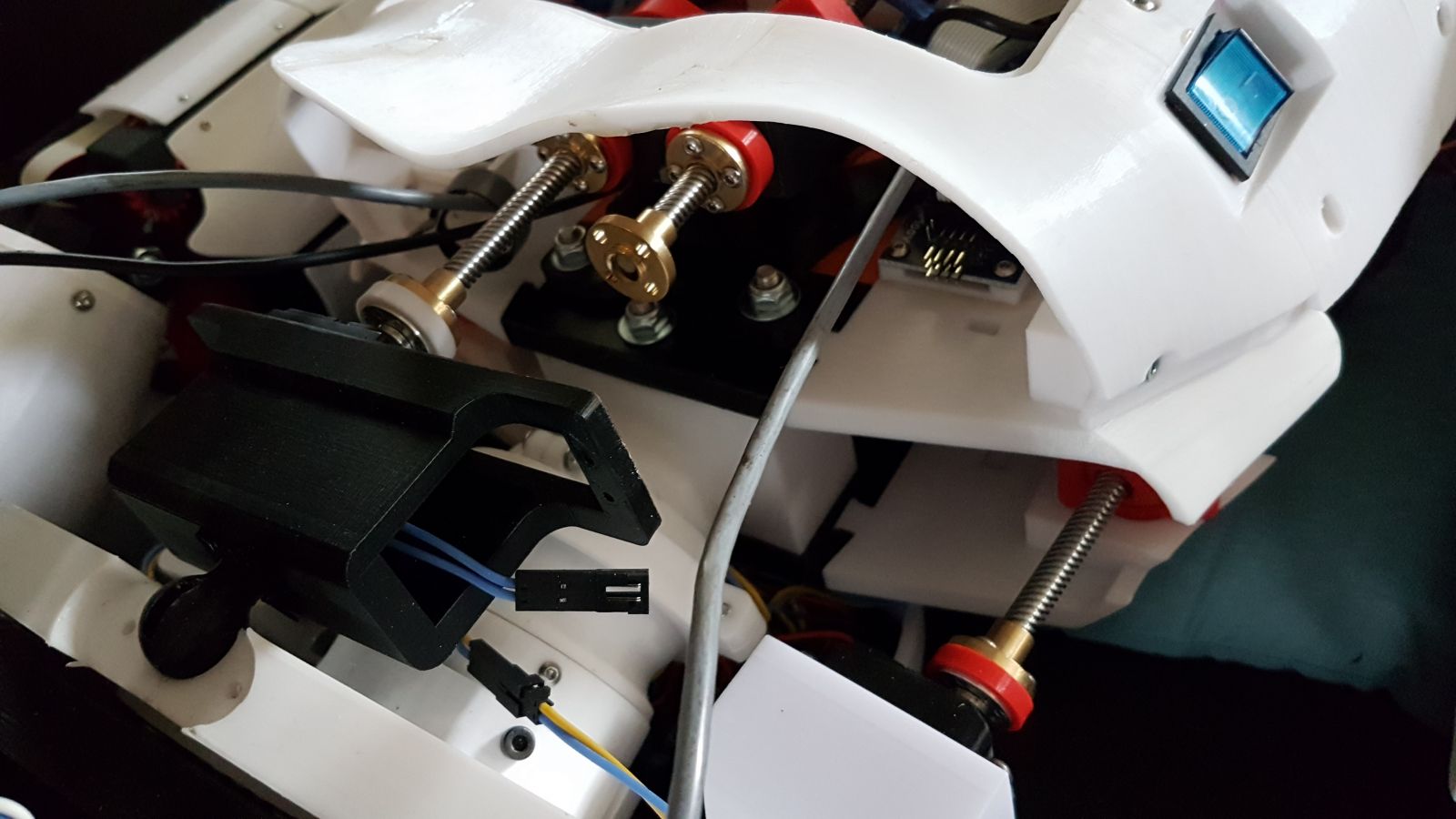
The next part to tackle is making the servos multi turn servos, The problem with that is how to feed back to the servos the angular position, In Gael's original design with 1 degree of freedom that was easy, having 2 degrees of freedom complicated finding a good solution for the potentiometers. some solutions were found on thingiverse but i thought the required brackets, bits and bobs looked out of place on the sleek Inmoov design.
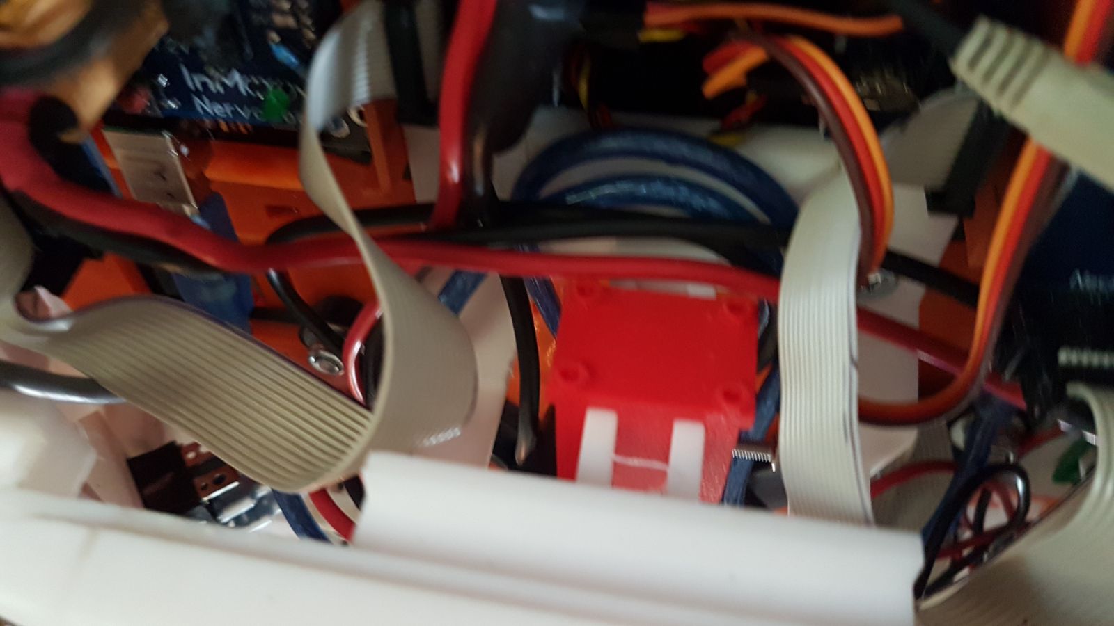
So, here is what I did. I took the potentiometers out of the servos and replaced them with 2 identical resistors, basically telling the servo the pot is always in the middle. Then I took a arduino nano and and have it capture the servo signals going to the stomach servos. The nano converts the PWM signal back into a desired servo angle. Next I am installing a BNO055 IMU sensor and measure the actual torso angle.
I subtract these signals which gives me an error signal in degrees. I add or subtract this from the theoretical servo center of 90 degrees. Remember the modified servo now always tries to reach 90 degrees because it has fixed resistors. This signal is converted back into a servo PWM signal and passed on to the servo. The result is that the system will follow the requested servo position.
I can do this for both backward/forward and side to side. I made a holder fo the BNO055 that stradles the center brace in the back of the robot, above the battery holder door. It is the little red saddle without the sensor on it.
I am currently playing with the software, I went from full PID to just P to PID but modified. The problem is that the servo has a dead band in which it will not move. I guess this is to prevent jitterring, So the PID controller innitially comes really close, but not quite spot on. At this point the Integral part starts acumulating and when the resulting PID signal exceeds the dead band the servo will suddenly move to a slightly new position. kinda flipflopping in jerks around the requested position. Only by a degree or so but on the distance between the pivot and the head, still very noticeable and I did not like that behavior.
so hence the modified PID with bounds set in, I am also going to add some cut-out relays, so when the lean limits are exceeded the power to the servos is cut off. Ahh, soo many things to play with..
One thing i could do, thanks Ray for planting this seed (being sarcastic here![]() ). is to also place an IMU in the head. this would then cause the head to hold the same angular position in space regardless of body tilt. Did i already say Soooo many things to play with.. lol
). is to also place an IMU in the head. this would then cause the head to hold the same angular position in space regardless of body tilt. Did i already say Soooo many things to play with.. lol
For those who do not know Kryten is an android robot in an english sitcom series called Red Dwarf who consistently creates problems and smart alec remarks .... sounds familiar? He even sprouts the obligatory center disk![]()


Now, if only I could find a
Now, if only I could find a 3D printable Kryten head .........
I'm not sure if you're serious...
Kryten's head is easy to find. There is a "Kryten Bust" online where the head is a separate part.
https://www.myminifactory.com/object/3d-print-red-dwarf-kryten-bust-60094
Hey OddBot!! I had not
Hey OddBot!!
I had not looked at the myminifactory yet.
Its one of these on the To Do list of things, get Inmoov head shaped like Kryten
Thanks for the link!!