
One of challenges with the old mapper was what to do when setting new values of min & max.
In the above diagram we see a range established by a min & max.
e.g. mapper = new Mapper(-1, 1, -1, 1)
min & max input will be -1 & 1 .. min & max output will be -1 & 1
In the diagram, if the new min value is @ position "value 1 or 2 " ... the result is well understood, but what if the new value is at position 3 ?
example of this is
mapper.setMin(2) .. what should happen ?
Should the min max switch ? Should nothing happen ie the value not be set ?
Mapping out the Mappers ! - I worked for probably too long on mapping all these details out, but in the end, when you require yourself to map it all out solutions begin to appear.
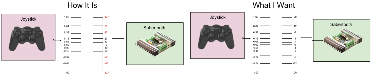
The Work-E robot kills furniture when the sabertooth motor controller operates higher than power value "20".
The Sabertooth's power range is -127 (full throttle backwards) to 127 (full throttle forwards).
The following is a list of diagrams "trying" to get "What I Want" - which is a mapping between the joystick and sabertooth which has maximal amount of control within a safe operating range.
.png)
It took some digging to see where this rabbit hole of data goes ..
fig.1 Is a diagram of how things would work without explicitly setting a mapper. There is a default mapper in the Sabertooth motor controller which maps -1.0 <=> 1.0 values to what the Sabertooth hardware requires -127 <=> 127. However, only a small range of motion of the Joystick doesn't fall in the valid, yet dangerous range of the Sabertooth. A Min Max is set, but doesn't affect the system at all, because I mistaken set it for Sabertooth values, not input values like setMinMax(-0.16, 0.16). Even if it was set properly, the mapping is not what I want, because I can't use the full range of the Joystick.
.png)
fig.2 Without thinking much, I decide to try to get the joystick mapper to map ranges. Of course this fails, because the joystick is "input" and its mapped values are correct output ranges, but they are used as "input" to the Sabertooth. In this mode any movement of the Joystick breaks furniture :P
.png)
fig. 3 The Joystick mapping was a mistake on my part, but a motor mapping "should have" worked. It didn't :(
Potentially, different motors on the same motor controller might need different mappings. It produced the correct "output" values, but as INPUT to the Sabertooth, and the Sabertooth has its own global mapping G(x) which came with the service. This global mapping is an attempt to provide a default worky mapping since the sabertooth requires the -127 to 127 range. Sadly, the incoming data goes through both mappings F(G(x)) and produces dangerous output from any Joystick movement :( ... Now any Joysticks data makes WORK-E slam into the wall.
.png)
This is the solution I'm thinking of trying to implement. The MotorControl never "calculates", but only supplies an alternate config (as a mapper) for the MotorController. So the controller simply checks to see if the MotorControl has a mapper, and if it does, the MotorController uses it. If the MotorControl does not have a mapper as config, the MotorController will uses its own global mapper.
This supports the following :
- The Sabertooth will still have its default global mapper, which will support default use .. goodtimes ..
- The Sabertooth could supply its default global mapper as config to any unset MotorControl mapper - allowing it later to be customized on an individual basis.
- Individual MotorControls can supply their "specialized" mapping, and the Sabertooth will use it instead of its global one.
I think this works well, except I see at least one problem. The setting of MinMax is done with mappings
leftMotor.setMinMax(-20, 20)
This would mean a mapper in MotorControl would be "set" - its default mapping is (-1, 1, -1, 1).
If this was done before attaching to the Sabertooth, the mapping would remain (-1, 1, -1, 1) and the end result would be not moving the motor because the final output would be too small, joystick values could end up on the serial line to the hardware.

This is to open the discussion of where we map values.
The use case is to operate a Motor using a Joystick.
This is the current flow :
Joystick == axis value ==> MotorControl.move( input ) ==> MotorController.moveMotor(input) ==> Hardware
My question is simple ... should MotorControl provide a mapper to be used for the final value which the MotorController sends to the hardware ?
I see comments in the code saying "not to do this".
However, "if" a power mapping is to be provided - a unique mapper will potentially be needed inside the MotorController for each MotorControl attached to the MotorController - this means the MotorController will need to identify each MotorControl and apply its specific mapper. To me, at this moment, it seems this would be simplified if each MotorControl motor stored its own mapper. But, that would go against the comments in the code ... can someone remind me "why" we don't want to do it this way ?
Speed Vs Power
In the real world, you want the joystick to control the speed of your motor.
The motor controller is controlling the power to the motor.
These are not the same thing....
What you really need is feed back from the motor to give you a current speed and then use a PID to control the power to the motor to archive the desired speed as requested by the joy stick
You can then limit the returned top speed based on a mapper from the joysticks to the speed controller.
Joystick -> Mapper -> PID(speed to power with speed feed back from motor) <-> Motor controller -> Motor
If you use the feed back loop with the PID then motor load caused by extra mass or the surface its running on, tiles, hardwood, carpet or grass won't affect the speed you trying to archive as the PID loop would automatically compensate.
Excellent input Ray, And I
Excellent input Ray,
And I agree .. but what if there is no feedback? ... you can say "There should always be feedback" .. yes that would be nice, but not always possible or practical.
Hey Grog, i once build my own
Hey Grog, i once build my own controller for a cnc machine and had to use power resistors to chop the current for the steppers. The same could be used to control dc motors.
I have some links that i found interesting at the time, maybe they can give you a lightbulb moment.
https://www.slideshare.net/AjeetaSrivastava/speed-control-of-dc-motor-u…
https://upcommons.upc.edu/bitstream/handle/2117/10703/Pedro6.pdf
https://www.electrical4u.com/speed-regulation-of-dc-motor/
Hope they can assist.
Wow, very detailed "choppin"
Wow, very detailed "choppin" ..
Cool wvantoorn, great resources ...
Servos And motors
Servos have a mapper. For consistency, I think motors should implement the same(similar)
Key use case, limit max power/speed, avoid headband. Goal is to get a near linear response from the motor movements.
Ah .. good .. I would agree
Ah .. good ..
I would agree - and when I was riding my bike I thought, "hmm... I should check to see what Servo does"
Cool, I wanted to do it this way, but was scared from the comments .. disregarding nagging code gossip now :)
deadband not headband
right.. avoid the deadband..
was thinking some non-linear transfer function something like a sigmoid function doing the mapping.
Interesting question GroG,
Interesting question GroG, without feedback I would say the mapper should be done by the joystick or controll system. With feedback (which I dont have yet but I have a potential place for an encoder) I guess it would be positive. But then there is the question if it should directly interact with the feedback or is it done by custom code?..
The Danger of Reducing Motor Power
There is a danger in reducing motor power power where power is being sent, however there is not enough to cause motor rotation.
In this case, you are relying on the resistance of the motor windings to limit the current.
Most motor controllers use a switch or chopped PWM signal to control the power, that means full volts are applied at timed intervals.
When a motor is rotating there is a back electromotive force generated by the motor that effectively increases the resistance of the motor.
With out the rotation, the motor can and will overheat (burn out) at very low power levels.
This is why a brownout is very back for motors in your house like in your fridge or freezer.
An example of how this can occur in a system with no feed back at all.
You setup your mapping with the power settings set on a smooth hard floor, all appears to work well.
You then drive on to a deep pile carpet where there is a lot more resistance to the wheels, or onto a slope, the upper end of the power is not high enough to overcome the resistance, so the motor sits there with power applied but no rotation. The motor is heating up rapidly.
There are quite a number of ways to get motor feedback, one of which is to monitor the current of the motor, this does require a more advance motor controller.
The easiest is a photo interrupter on the wheel shaft, or better still on the motor before it goes into the gearbox.
Alternatively you could always use an accelerometer to pick up movement....
@Ray, you have gems of
@Ray, you have gems of wisdom from real experience .. thankfully I'll get to review them before working on feedback, but right now I need to get the kinks out of the simple "control" paths
We'll want to try to support
@Kakadu - We'll want to try to support the most generic form of feedback in this control system - a simple path of data which represents the "actual" motor position (relative or absolute).
Details of the the feedback will only need to supply configuration to support the users specific system.
Before we do that, the "control" path should be satisfactory ... it's not yet .. :)
transfer functions for the win!
You've been in Neural Nets
You've been in Neural Nets for too long ! :D
Some things actually "want" linear transformations.. I guess what your saying is we could use a sigmoid to express linear "and" non linear functions .. which would be cool ..
Sure !
pluggable transfer function in the mapper
I think for the short term, a linear mapping is probably fine. so long as it's pluggable and we can add other transfer functions like a sigmoid or a piecewise linear transfer function that looks like this one on it's side.
https://www.electronics-tutorials.ws/amplifier/amp48.gif
For me this problem seems very framiliar and is similar to the "crossover distortion" that occurs in an AB class amplifier with a push/pull output.
I believe that MotorControl
I believe that MotorControl should represent a big wad of data which MotorController uses to provide the correct action.
It makes sense that MotorControl should contain all data for an individual Motor, and this fits with the many to one relationship of Motor to MotorController. One motor controller potentially can control many motors, each motor may need its own "specialized" data or configuration to run correctly.
Motor control provides the methods to control the motor - but all methods proxy to MotorController ..
motor.move(0.32) => internally is always motorController.motorMove(this)
Data isn't passed through MotorControl .. rather data is set, and the reference of the whole MotorControl is sent to the MotorController.
All functions only take MotorControl as a parameter (happily this is how all the functions signatures are currently defined)
Now I just got to trim the weeds down around it ..
AbstractMotor the mother of
AbstractMotor the mother of all Motors - the implementor of MotorControl ....
just lost its mapper(s) ... All of them ! CHOP !
It now has minX maxX minY and maxY values - so it has the data to be a mapper, but does not contain one.
AbstractMotorController will use the data in AbstractMotor to map if (minX, .. etc) is set, if these values are not set they will be set them with default values provided by the controller.
In this way - the controller has the opportunity to set intelligent values if they are not set. MotorControl has highest priority for setting values, and the order of them being set does'nt matter, because default is only set if their initial values are null.
The New MotorControl Law
First Law of MotorControl :
Hypothetical control setup
Hello Grog.
Just some food for thought that may help or confuse with your programming.
In this hypothetical setup, we have custom built joystick and two motor controllers.
Each motor drives a wheel, one on the left and one on the right.
The speed controllers attached to each of the motors take in serial data with a speed setting in the range -127 to 127 with 0 being stopped.
The left motor has a positive number to make our robot go forward and a negative number to go back.
The right motor has a negative number to go forward and a positive number to go back.
The joysticks are configured in an X and Y axis with a spring return to middle on the X and a spring return to about a third on the Y.
The returned values from the joystick, via an Arduino Nano is as follows.
The X is a range or 0 to 1023 with 0 being all the way left and 1023 all the way right.
The spring return however is not always center with a range of 505 to 515 when the stick is let go.
The Y range is 0 to 1023 with 0 being all the way back and 1023 being all the way forward.
The spring return however take it to a position where it returns between 295 and 314 when the stick is let go.
The maker who could not change the wires on his right motor also wants the motors to not exceed 40 on the drive power in forward or 20 in reverse, hes not real good in backing up.
The output of the joystick has to be mapped to both the motors with the Y axis controlling forward and back and X mixing in to control the turning, a skid steer setup.
For this we need the mapper component to be able to provide the mixing from the X channel of the joystick and also handle the dead band from the joystick as well as inverting the signal to the right motor.
This would maybe even a good
This would maybe even a good point to start an implemental steering of 2 motors with 1 joystick like I use it at the moment. If the converter is standardized it my be more simple to do a default mapper.