With my leg project, I will use absolute encoder instead of potentiometers. During my research, I've found an interesting "cheap" encoder from CUI. The AMT-203. Arduino can "speak" with it by the use of the SPI bus.

I've found a sample code which is working for me.
It comes from the arduino forum :
http://forum.arduino.cc/index.php?topic=158790.0
here's the code :
#include <SPI.h>
#define CS 3 //Chip or Slave select
uint16_t ABSposition = 0;
uint16_t ABSposition_last = 0;
uint8_t temp[2]; //This one.
float deg = 0.00;
void setup()
{
pinMode(CS,OUTPUT);//Slave Select
digitalWrite(CS,HIGH);
SPI.begin();
SPI.setBitOrder(MSBFIRST);
SPI.setDataMode(SPI_MODE0);
SPI.setClockDivider(SPI_CLOCK_DIV32);
Serial.begin(115200);
Serial.println("starting");
Serial.flush();
delay(2000);
SPI.end();
}
uint8_t SPI_T (uint8_t msg) //Repetive SPI transmit sequence
{
uint8_t msg_temp = 0; //vairable to hold recieved data
digitalWrite(CS,LOW); //select spi device
msg_temp = SPI.transfer(msg); //send and recieve
digitalWrite(CS,HIGH); //deselect spi device
return(msg_temp); //return recieved byte
}
void loop()
{
uint8_t recieved = 0xA5; //just a temp vairable
ABSposition = 0; //reset position vairable
SPI.begin(); //start transmition
digitalWrite(CS,LOW);
SPI_T(0x10); //issue read command
recieved = SPI_T(0x00); //issue NOP to check if encoder is ready to send
while (recieved != 0x10) //loop while encoder is not ready to send
{
recieved = SPI_T(0x00); //cleck again if encoder is still working
delay(2); //wait a bit
}
temp[0] = SPI_T(0x00); //Recieve MSB
temp[1] = SPI_T(0x00); // recieve LSB
digitalWrite(CS,HIGH); //just to make sure
SPI.end(); //end transmition
temp[0] &=~ 0xF0; //mask out the first 4 bits
ABSposition = temp[0] << 8; //shift MSB to correct ABSposition in ABSposition message
ABSposition += temp[1]; // add LSB to ABSposition message to complete message
if (ABSposition != ABSposition_last) //if nothing has changed dont wast time sending position
{
ABSposition_last = ABSposition; //set last position to current position
deg = ABSposition;
deg = deg * 0.08789; // aprox 360/4096
Serial.println(deg); //send position in degrees
}
delay(10); //wait a bit till next check
}
Note that the code is written to use the SPI on the ISCP connector (MOSI, MISO, SCK)
(tested with arduino UNO)
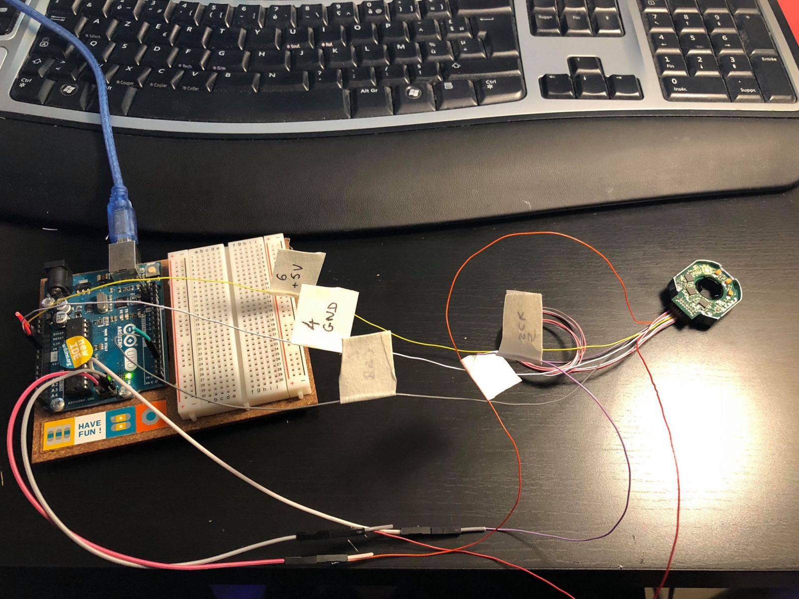
As you can the on the picutre below, the code returns the angular position of the encoder (0-360 degrees).
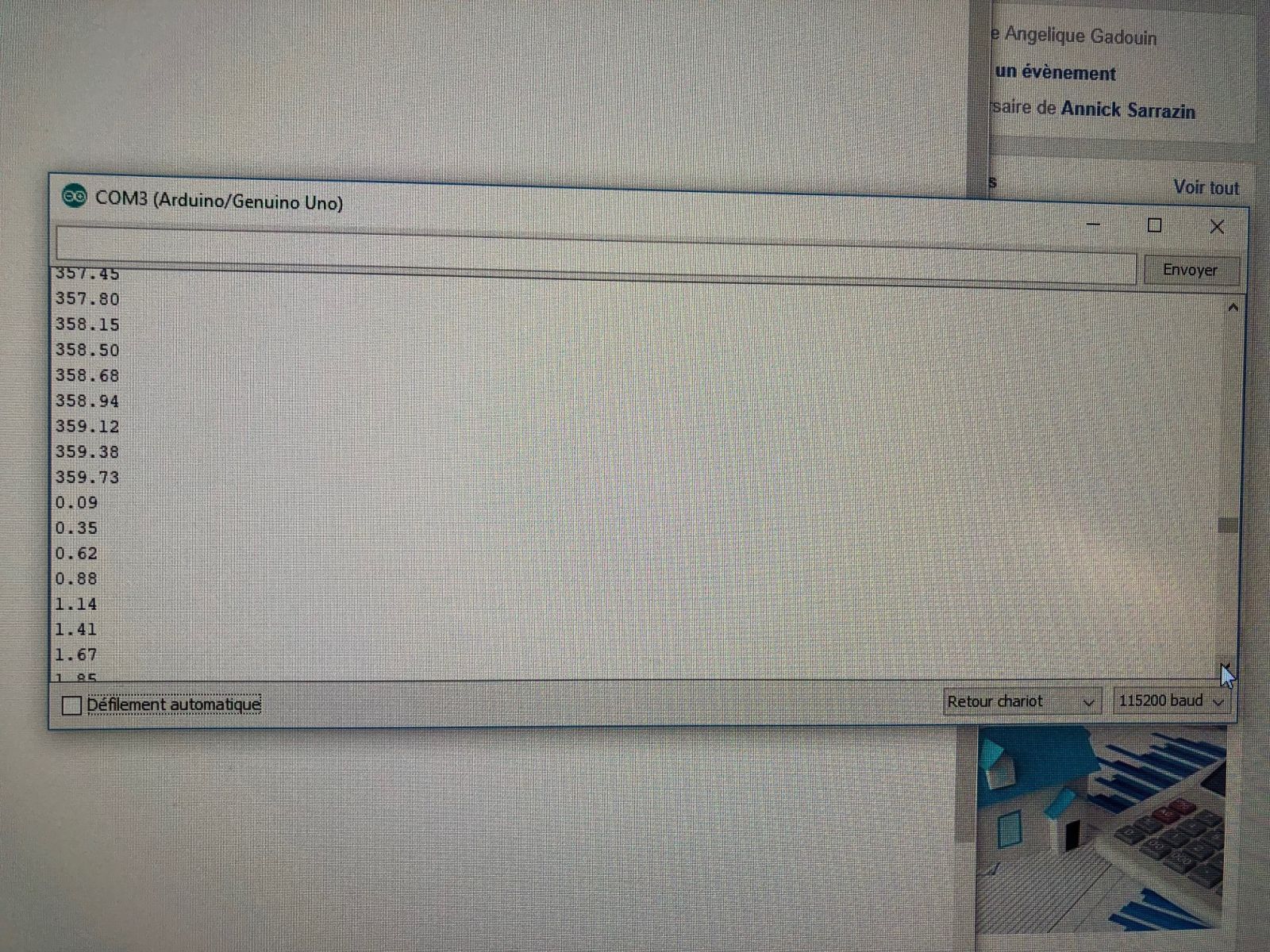
Ready to use on legs !
So Kevin, you can now try to add it in MRL :)
Great Post Bretzel. I
Great Post Bretzel.
I haven't looked into the details of this new sensor.
Aren't potentiometers absolute ? (if they are not to sloppy) ;) - If thats the case then why couldn't you use a potentiometer ?
It looks to be a 12 bit absolute encoder - what are the colored plastic things? Collets for shafts ?
I couldn't find much examples of mounting it besides this one.
Bye the way - your design drawings are gorgeous and should be in movies like the one below ;)
Thanks ! I would like to use
Thanks ! I would like to use something more accurate and I think this thing could be great for the price :)
The colored rings are shaft adapter with differents diameter.
I hope I can do some tests soon :)
MrlDevice and CUI encoder support on it's way!
This is great Bretzel! Thanks so much for sharing and bringing this device to our attention. I ordered up a few to test with , hopefully they'll arrive in a few days.
I am really excited to try these out because I'm hoping for a few things that are major benefits over a potentiometer.
1. they'are actually linear!
2. they shouldn't need to be calibrated! (aside from setting where "zero" is once and burning it in.
3. they (hopefully) won't be affected by electric pwm noise!
They're a lot more expensive than a potentiometer, but I'm also hoping they're more accurate and less prone to error.
These will be the first SPI device supported in MrlComm, I suspect they will evolve over time... Once I've had a chance to play with them a bit, the elves will get to work to hammer it into some nice low level support for this as a feedback mechanism for the DiyServo!
The ultimate goal is that these will be 1 click worky for DiyServo! I'm really looking forward to trying these out.
encoders
I definitely think encoders are the way to go for good accuracy. On my hiip motor the out put shaft turns 52 rpm. The resolution from the encoders is 2400 pulses per revolution. So you can adjust the output to close to 0.15 degrees of a revolution, if my math is right. I currently have the dead zone at +/- 5 degrees which gives back a little. Running in absolute mode you send a command to a motor and expect the motor to be there. When I was lifting marbles with Azul, moving the arms, shoulders, waist, and hands the resolution was very poor. All of those motors are servos. I ended up putting a spring on the finger so it wouldn't knock off the marble when picking it up. You can watch it on Youtub, and yes it is more expensive.
Your drawings are very nice. What CAD system are you using?
Is this incorporated into MRL?
I have a couple of dumb questions:
Do these encoders need to be incorporated as MRL services?
Has it been done yet?
Will it be done (as in should I start working on this)?
Those images are really impressive and beautiful. Did you do them with Blender?
Thanks for your work.
-Annie
I think @kwatters has already
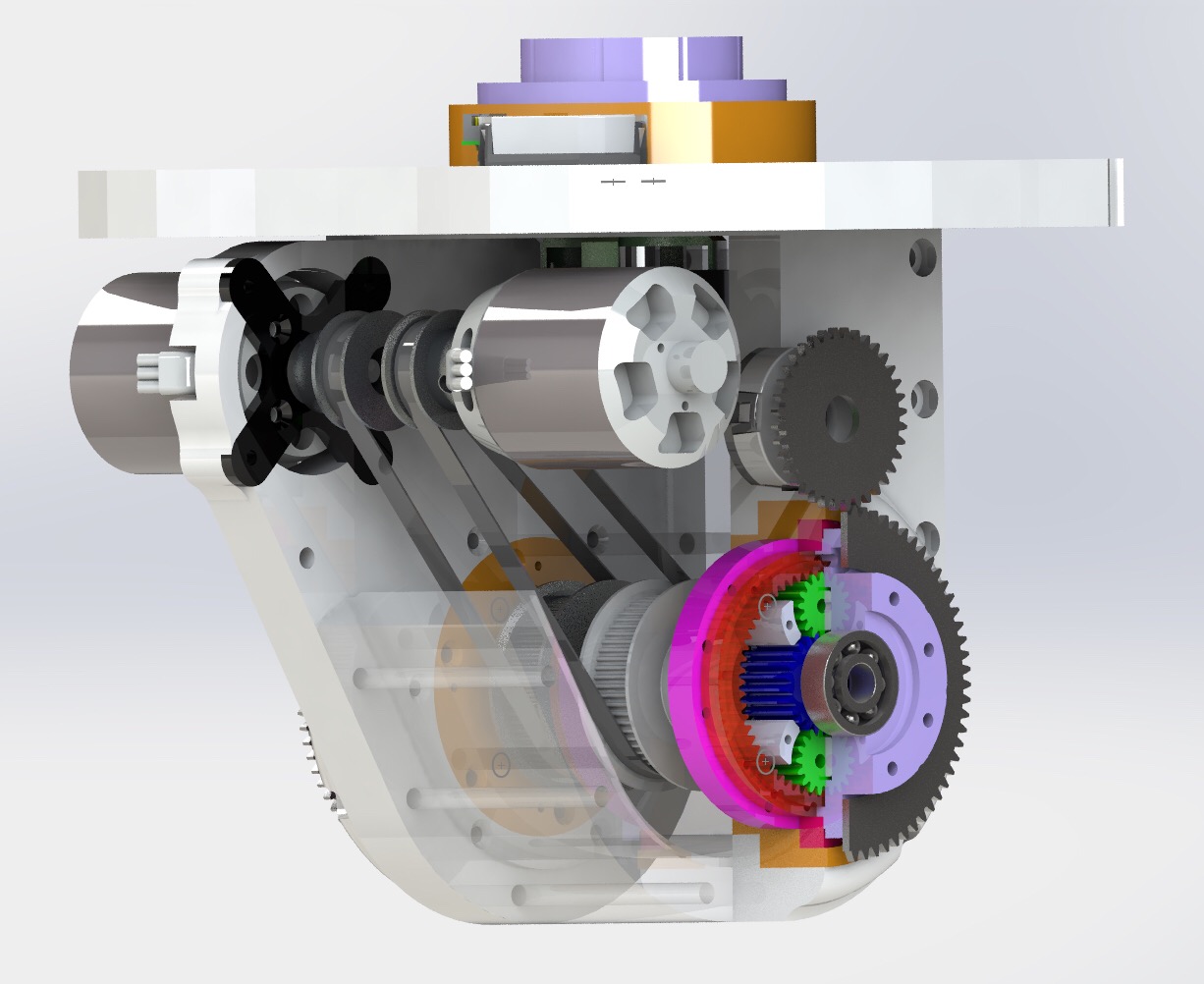
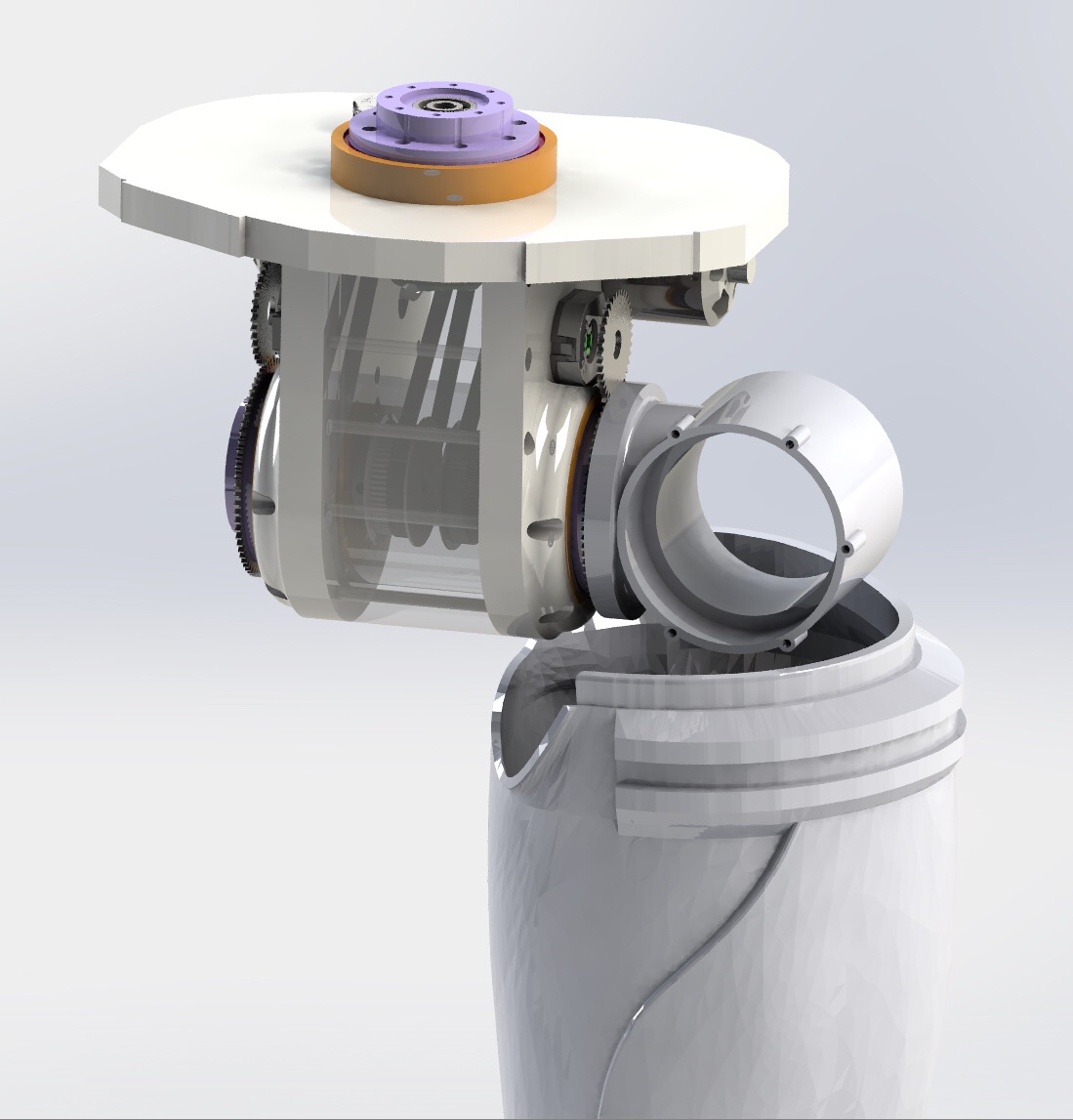
I’m using solidworks.about
I’m using solidworks.
about speed, it depends on the ratio. Speed will be 43 and 21.5 RPM. So 0.23s and 0.46s per 60 degrees.
@ 12V. Motor can support 24V. So speed can be X 2
Very nice :) What motor type
Very nice :)
What motor type are you using ? i have very big fate in this project so will order up
some motors and encoders :)
I’m using R/C BLDC motors.
I’m using R/C BLDC motors.
Yup, But what size / type are
Yup,
But what size / type are you using ? :)
It's a Turnigy SK3 from
It's a Turnigy SK3 from Hobbyking. 350Kv
some hours
some hours later...
happy with the result even very first alpha design :)
Just for fun :
Just for fun :
This is so nice, looking
This is so nice, looking forwared to see it spinning :)
Nice ! .. Quality work
Nice ! ..
Quality work Bretzel !
(The yellow thong suites him ;)
Here Is my first gear rings
Here Is my first gear rings prototype :
Very nice Bretzel_59, This is
Very nice Bretzel_59,
This is the only thing that worries me, where do we get those, is it a new steel filament, lol :D
Gears are made by EDM wire
Gears are made by EDM wire cutting ($$$$). I think it could be possible to print these gears with Nylon filament, maybe enough for standard walking. but I want the robot to be able to squat, this is the most torque requirement position.
Boston Dynamics ? lol
Let’s go !
Let’s go !
Orderd up 2 CUI
Orderd up 2
CUI AMT203
From mouser today, an also a nice microphone array :)
BLDC motors are next..
Great :) It remains some
Great :)
It remains some work to make it working :)
https://youtu.be/ZwA-2pmvz7U
Looks sweet Bretzel_59
Looks sweet Bretzel_59 :)
Later when you are ready, would it be possible to buy the metal "set's" (group buy) together, the price for the jobb wil probaly come down, but it might work in nylon as you said :)
Do you just use a normal pwm
Do you just use a normal pwm rc esc for the motors Bretzel ? or are you using something else ?
Yes, with reverse capability.
Yes, with reverse capability.
Yes,Have been looking at
Yes,
Have been looking at this one, 80amp (90 for 10sec) but from the drone world i know a motor can easely
doubble and more it's power consumtion for a short time, this one might be to small, what do you think ?
https://hobbyking.com/en_us/aerostar-rvs-80a-electronic-speed-controlle…
Seems this model is not
Seems this model is not really good for what we want to do :
Warning: Reverse function should not be activated until the motor comes to a completed stop. Otherwise it will damage both motor & ESC.
In the manual, you can read you need a switch for reverse. I use RC car ESC which have foward/reverse mode with no pause. this one :
https://hobbyking.com/en_us/hobbykingr-tm-x-car-60a-brushless-car-esc-s…
I have done a huge stock at home (22 of them). Yes I am crazy , but in the future, and if my solution works, I want to replace servos in torso and arms with my gearboxes and brushless motors :)
So need to secure ESC stock at home :)
I'm limited to 3S but it's OK for what I want to do.
Ah, a rc car esc, yes they
Ah, a rc car esc, yes they can normaly be reversed just when you want to.
22 pices, lol :)
This ESC has a switch. so
This ESC has a switch. so with a little hack, it could be possible to power on/off each actuator with an Arduino.
Nice :) So, since i need 4s,
Nice :)
So, since i need 4s, what do you think about this one :
https://hobbyking.com/en_us/hobbykingr-tmbrushless-car-esc-100a-w-rever…
I think it’s fine, you have
I think it’s fine, you have to use run mode two instead run mode two2
Thanks for the help
Thanks for the help Bretzel_59 :)
Hi bretzel_59, Do you have a
Hi bretzel_59,
Do you have a link to the pulley's and the belt type you are using ? :)
and maybe some of the bearings ?
Pulleys are standard GT2 with
Pulleys are standard GT2 with 6mm width gt2 belt. ratio is 1:2 or 1:3 (30:60 or 20:60). lenght needs to be determined.
Borged
Thanks for the code Bretzel. I added a new Amt203Encoder service to MyRobotLab that you can attach to an arduino. It assumes that you connect the SPI, this means
+5V / Ground / CSK / MOSI / MISO and lastly a digital pin for the CSB (chip select)
https://github.com/MyRobotLab/myrobotlab/commit/03e930eb548a31482bfd83d…
This checkin only supports 1 encoder at the moment, so we'll need to see about abstracting it away and making it support as many encoders are you have pins for.
There are some very interesting lessons that I learned about implementing this device support in MRL.
First is, a lot of the code for it, (both Java and CPP) is generated from a schema. Add your methods to the schema and you're good to go.
second, there's a set of shaddow classes in java that mimic the cpp arduino classes. These are used for virtual arduino support
third, we needed a subclass of service for this new device. Behold the Amt203Encoder service.
fourth, implementing this new device type/service was made easier by implementing new interfaces EncoderController and EncoderControl. The arduino is an EncoderController and the encoder service is an EncoderControl.
fifth, don't panic
AMT203-V cable?
Hi there. I have a question about the AMT203-V encoder you are using. I have one too. How do you wire it up? ( as my dupont cables/jumper wires seem too big? I've seen the data sheet refers to the Samtec ISDF-07-D adapter but I've never used this before and don't know how to wire it up. Any advice? Thanks.
Connectors are difficult to connect
The AMT203-V has very small pins and it's difficult to wire them up. I tried for a while, but didn't do very well. Fortunately you can buy an adapter cable that give you the ISDF-07-D adapter with the wires already plugged into it.
I got mine from Digikey, (not cheap.. unfortunately, )
Here's a link to the cable I'm talking about:
https://www.digikey.com/product-detail/en/cui-inc/AMT-14C-0-036-2/CP-AM…
I'm sure folks with better soldering skills that I have could make their own..
Hi there Many thanks for the
Hi there
Many thanks for the link. You're right...it's not cheap!!