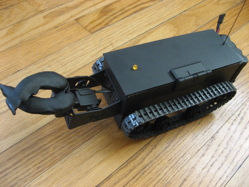
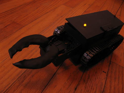
Bug Toy is a simple radio controlled robot. It is part of the distributed robot Audrey.
With Mood Lighting
Chassis, Wheels, and Tracks
1 x #61 Tamiya 70097 Twin-Motor Gearbox Kit = 8.95
1 x #106 Tamiya 70100 Track and Wheel Set = 9.50
1 x #79 Tamiya 70098 Universal Plate Set = 6.25
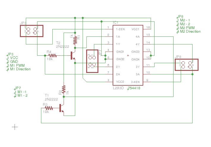
Motor Driver754410 Dual H-Bridge IC DataSheet
Mini-BOA H-Bridge (Relay + Tip122)
Communication
RF Link 2400bps Receiver - 434MHz - using Arduino library VirtualWire
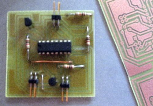
Bug Toy's Guts
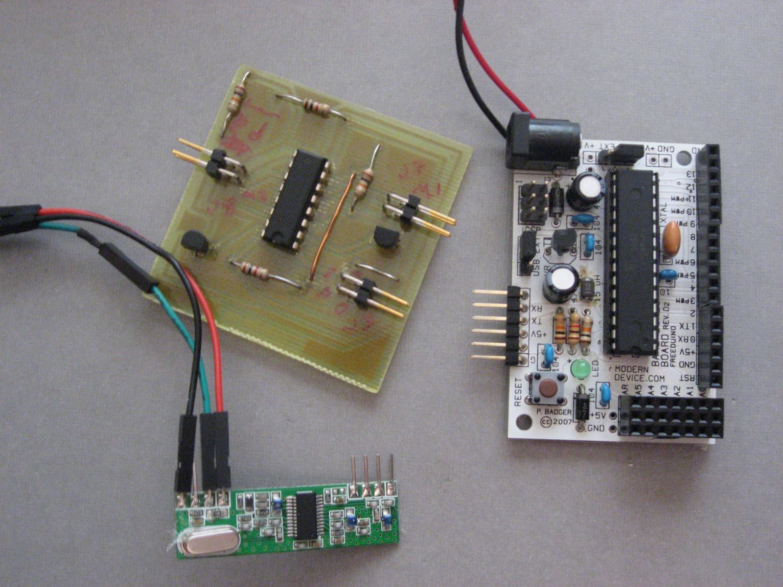
Here are the guts of the Bug Toy. The 3 types of electronic parts used in this project are a motor controller, a micro-controller, and a RF module. The motor controller allows the motors to turn in the appropriate direction and speed. The motor controller is controlled by the micro-controller, which is the Bug Toys brain. The RF module is also connected to the microcontroller. It receives instructions on what to do from my home computer. The code running on the micro-controller in Bug Toy is fairly simple. It reads the data from the RF module and executes the appropriate action.
Home Computer and RF Transmitter
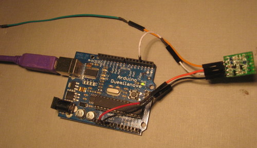
The transmitter is connected to my original Arduino (notice the burned out cap :P - still works though). MyRobotLab runs on the home computer and does all the video processing, voice recognition, joystick, internet connectivity and other synchronizing. Commands are sent via USB to this Arduino, then transmitted to Bug Toy.
I had some issues with my original motor controller, so I redesigned it. So far, I have had no problems with the second design. It was inspired by BaseOverApex's design at letsmakerobots. He designed a controller to drive a very large load. I scaled down the components, and exchanged the FET with a common TIP122.
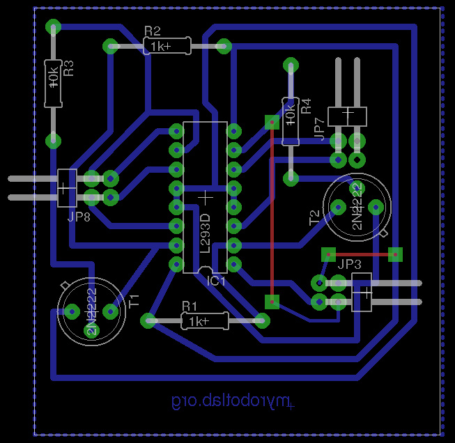
Motor Driver Schematic
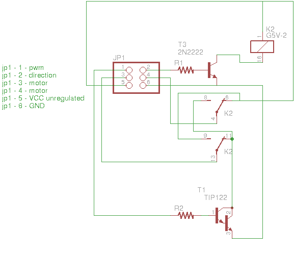
Motor Driver Schematic (retired)
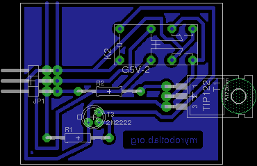
Motor Driver Art (retired)
Lessons learned. Don't "Print" From Eagle Cad to pdf or ps to toner transfer, the images are not too good and they have blurry edges. Its much better to "Export" to an png. Eagle exports inverted, probably for UV printing. I was unable to invert in Eagle but GIMP was very useful as usual and got the job done.
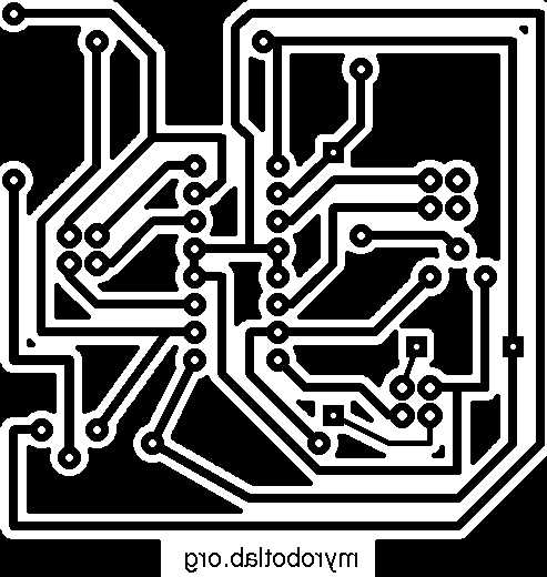
Etched 2 - Bit 754410 Motor Controller
The 754410 seemed like a good choice for a motor controller, except it was a 4 bridge chip and would take 4 data lines to drive. In some cases with large motors you might want to do high-side, low-side or regenerative braking. But, with small motors, I don't see the point in having to control all 4 gates, so I added a few resistors and transistors to turn it into a 2-Bit controller 1 bit for PWM and 1 bit for direction.
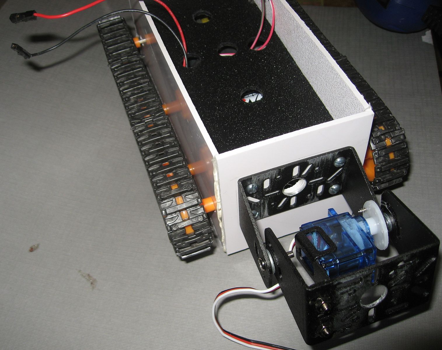
Tamiya Gear Motors
From previous failures I finally figured out what I was looking for, "A extremely low rpm high torque gear motor". The Tamiya dual gear motor seemed like a good fit. 204:1 is a good ratio. When it arrived, I was a little surprised it needed to be assembled. It was really quite "fun" to put all the gears together and follow the very detailed picture diagrams.
In the end the high torque to low rpm was great but there were a couple problems. The biggest was a irritating squeal and loud chatter. Searching the web, it seemed others had this problem too. Some thought of adding a washer to the first gear to push it closer to the motor. I pushed the gear with my finger closer to the motor and the noise substantially decreased in volume. So, I disassembled the whole thing to put on one of the smallest washers on hand, only to find out the housing would not close properly. That did not work.
The working solution came in the form of the same washer, but shoved between the two motors. This made the gears on the motors come into full contact with the first cog gears. I also added a huge glob of Vaseline to gears. Now the noise is much much more tolerable.
.JPG)
PVC Plastic Sheets
I saw some great work done with PCB as a structural steam punk material. Unfortunately, I was too heavily invested in PVC scrap from a local plastic store ($1/lbs). With a saw and some hot glue, the body began to take shape. PVC will bond well with any glue containing cyanoacrylate (superglue). Underneath the black deck are the batteries and Tamiya gearmotors. Electronics will go on top.
Power Distribution Plugs
If you don't want to commit a breadboard to your bot, but need to break out multiple power and ground cables this quick little plug can be very helpful. Just solder a set of male jumpers and bath all the parts you don't want exposed in hot glue.
.JPG)
References
- Great quick reference on transistor logic
- Ground Plane Eagle Tutorial
- Instructables Eagle CAD configuration for DIY PCBs
| Pin# | Function | Comments |
|---|---|---|
| 0 | RX | |
| 1 | TX | |
| 2 | ||
| 3 | Right Power | |
| 4 | ||
| 5 | Right Direction |
PWM is out on this pin, possibly a VirtualWire conflict Low = Forward |
| 6 | Left Power | |
| 7 | Left Direction | |
| 8 | Virtual Wire RX | |
| 9 | ||
| 10 | ||
| 11 | ||
| 12 | Servo1 | |
| 13 | Servo2 |
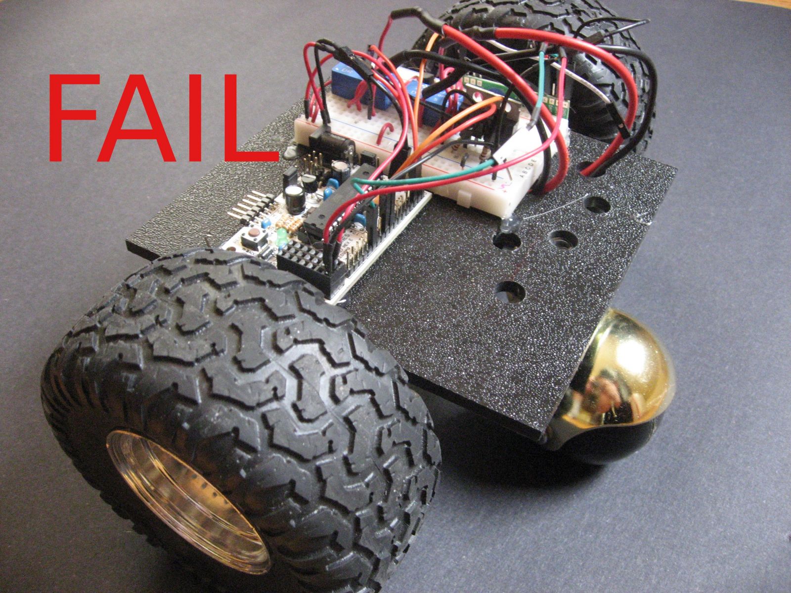
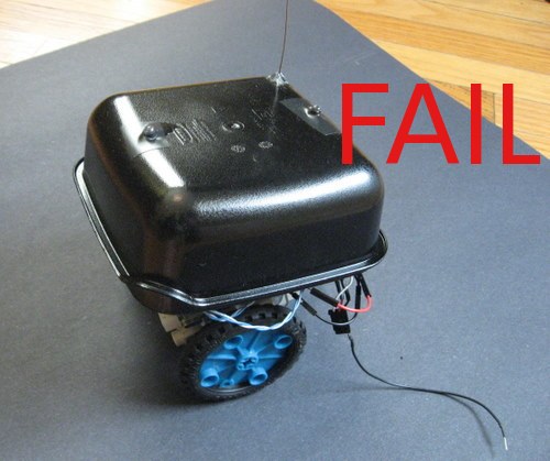
Nothing Worked? Don't Worry, I have days like that too.
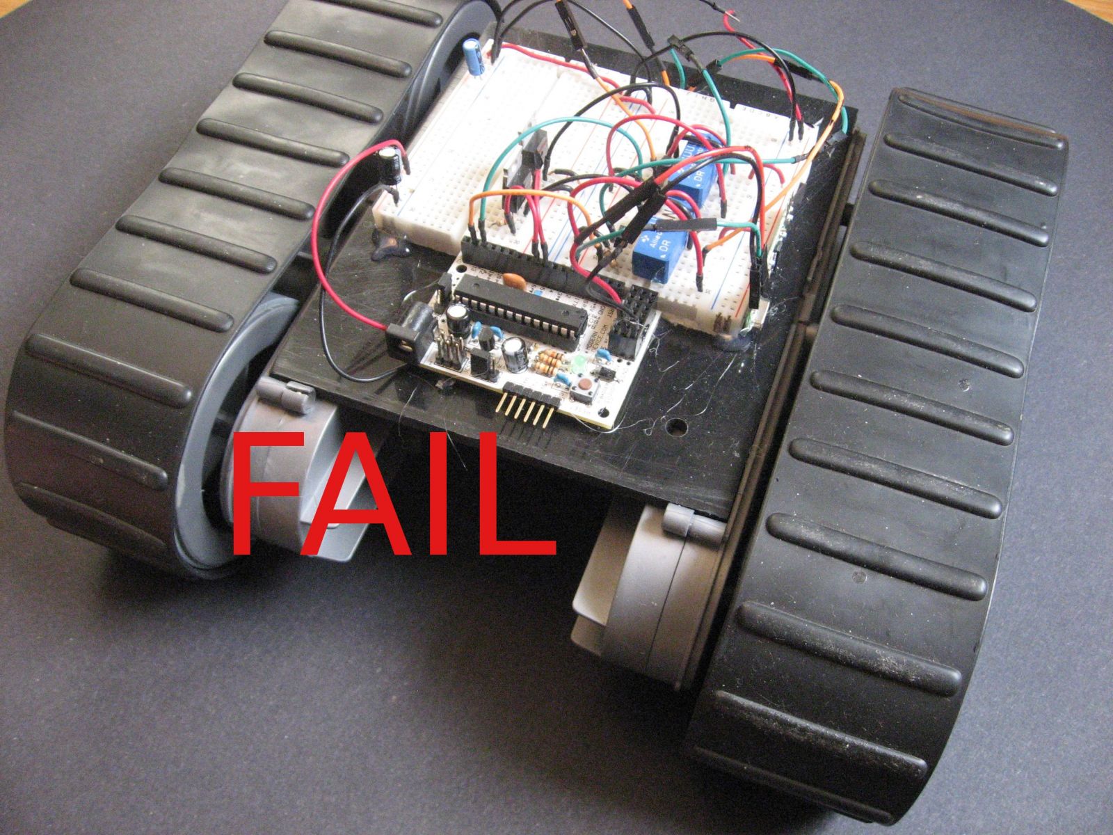
Treads came from a salvaged toy. Although the tiny gear motors maintained a good speed the treads were very poorly made and interfered with accurate mobility. A possible solution would be to cut the tracks and wrap each power wheel, so it became a tire instead of a tread.
The found caster worked well, and the turning radius was quite nice. The problem came from having to over power the gear motors to get them to moving. The PWM needed to initially move the motors made them go way to fast. I preferred not going through the complexity of dealing with this problem in software. Someone suggested that I grease the gearbox. This might be worthwhile in the future, although, I was not able to find a easy way to open the gearbox.
The motors, wheels, and gearboxes all came from the same Lego like kit. This was "close" to successful. The power system did not brown out when the motors stalled. I don't think the motors were very electrically noisy as communication was fairly robust. The speed was pretty slow which was desirable, however there was a considerable amount of overshoot.