To display IK i've been trying to decide between Java3D(old and no longer supported or developed), JavaFX (new engine from Oracle), & WebGL + Three.js - Looking around I found this ! (wow - very nice !)
More interesting WebGL IK Information - http://www.kadrmasconcepts.com/blog/tag/webgl/
Another one from the same author - http://www.akjava.com/demo/poseeditor/

Step 2: Get the data
We need detailed information regarding InMoov so we can use it in Inverse Kinematics & Forward Kinematics.
Hopefully Gael will be able to provide us with information too. First this will be driving a mathmatical model of the InMoov - then we will be able to choose a point in space and have InMoov grab at that location.
After we find the mathmatical model working and behaving correctly, we can continue to add software to visualize the model. This will be InMoov image of himself ;) It would be a very big leap to be able to have simulations and emulations with or without hardware.
In trying to solve the problem - the first step is defining the problem.
Step 1: The Problem
Sketchup Fixed: - now to find the "CORRECT ANSWER" and work backwards :)
|
Sketchup Import |
 |

Update 2014.04.26
 |
The image to the left looks like the values could be "correct" |
| But once the arms travel past the 90 degree yz point - i think the omoplates go to 180 |
 |
Had to do a lot of refactoring. OpenNI service and SimpleOpenNI had a lot of problems, and the data it created was not very easy to extend. Now it operates very similarly to the OpenCV service in that an OpenNIData object is created for each frame and reference to the rgb, depth, and ir images are all in there. This will make it easier to pass data from OpenNI into OpenCV.

Now we can save out a single frame too with the calculated angles, xyz positions too. This frame I said "save frame" - and the small script we have will save it without the need of using a keyboard. As it looks now XY is omoplate - left is currently at 9 and right is 4.. InMoov shoulders are tied to YZ - now 81 for left and 94 for right.

Wayne and I are trying to get the math & joints working correctly and accurately.
To that end we are starting a diagnostic script which we will develop to analyze math and verify angles and measurements.
Link to script :
https://docs.google.com/document/d/1IJE8x8PWpLgP0MSkgMNozTBrr2H_T43cC_v…;
Input from anyone is welcome ! Remember Math can be FUN !!!


You should start it up - it
Run Python Script
You should start it up - it "should" do the capture gesture skeleton and you should be able to move around your left arm - after moving it a couple times you should quit the program and there will be a a new ruby sketch.
After the file has been created you can import it into Sketchup by starting the ruby console and loading the file.
Starting Ruby Console
Display the Ruby console by select Window > Ruby Console
Load Ruby Data File
e.g.
load 'c:\myrobotlab\myrobotlab1987\skeleton_1398286307394.rb'
(No subject)
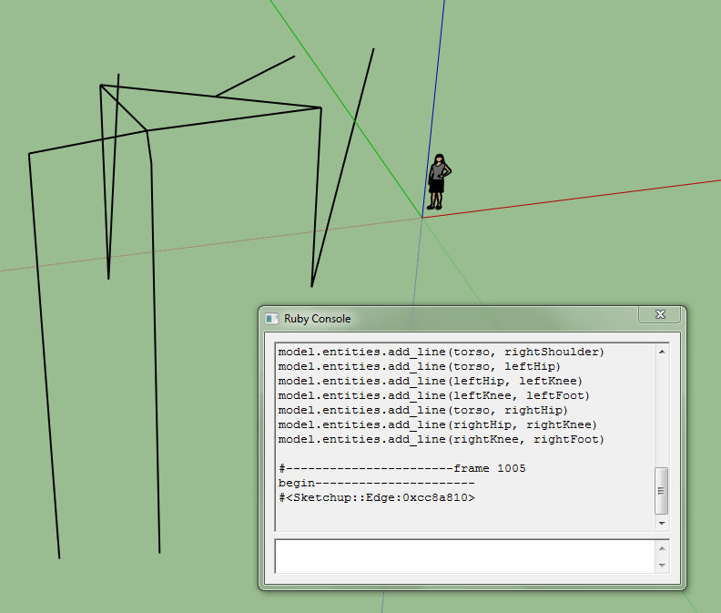
Frame 1005 out of 1800 -
Frame 1005 out of 1800 - Looks like WK is getting close to the kinect. The little lady & orgin "should" be where the kinect is .. I think... So things we are missing we have the xyz coordinates of all the lines, the lines in 3 dimensions - we could start measuring the angles with the protractor tool in sketchup - but we are missing the current servo values and the image itself, and knowledge of what the heck wk is doing and the interpretation of how the servos are behaving .. e.g. omoplate is bad now...
Some measurements to get
Some measurements to get started. I will add more as soon as I have a some time off.
(No subject)
(No subject)
(No subject)
(No subject)
(No subject)
(No subject)
(No subject)