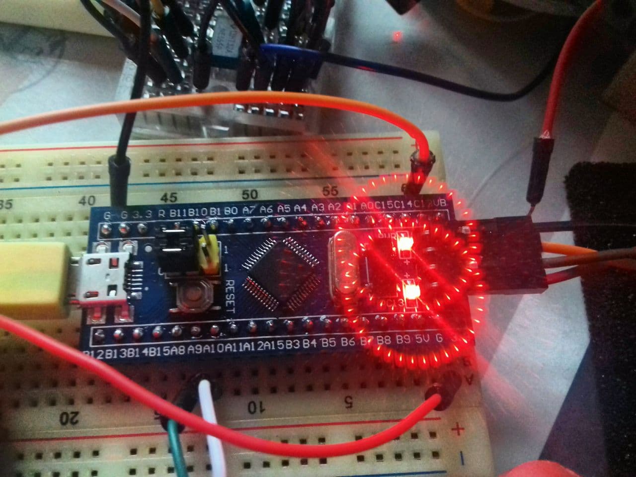
The MCU you see above is know as the "Blue-Pill" , it belongs to the STM32 family.
To put it in simple terms.... its a bit like an Arduino on steroids.
STM32F103 Specs :-
- ARM®Cortex®-M3 32-bit RISC core operating at a 72 MHz frequency,
- Flash memory up to 128 Kbytes and
- SRAM up to 20 Kbytes
- 26/37/51/80 I/Os, all mappable on 16 external interrupt vectors and almost all 5 V-tolerant
- 2x APB buses.
- 7-channel DMA controller
- 2x 12-bit ADCs,
- 3x 16-bit timers, each with up to 4 IC/OC/PWM or pulse counter and quadrature (incremental) encoder input
- 2x I2Cs and SPIs,
- 3xUSARTs,
- 1 USB 2 bus
- 1 CAN bus
- Serial wire debug (SWD) & JTAG interfaces
The STM32 sits in-between the Arduino and ESP32 Microprocessors (leans more towards the Arduino roughly, without the ESP32's Bluetooth and wifi).
The Generic STM32's can be picked up for a very low price, however getting a good one from the rabbit warren of vendors is a nightmare as there are many traps for the uninitiated.
The easiest way to program the STM32 is by using a ST-Link v2 programming dongle
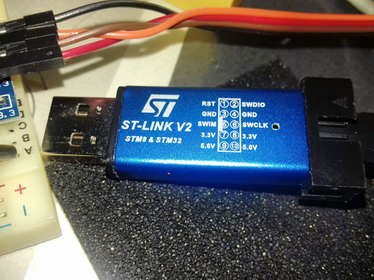
Its a simple case of wiring up the 4 pins of the dongle 3.3V, 0V, SWCLK and SWDIO to the corresponding pins of the STM32.
Head over to the STMicroelectronis site. Here is a plethora or tools and development aids.
(Tip .... I found creating a user account simplifies downloading of the software).
To get up and running a good general starting point is to use the STM32 CUBE Programmer
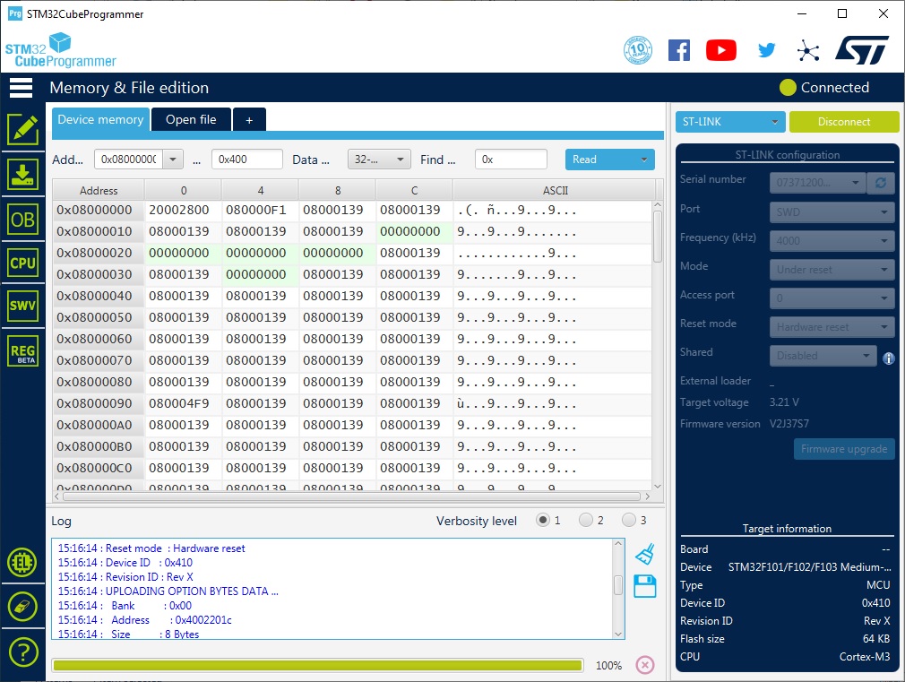
Which will give quite a bit of control over Up/down loading its contents etcetera.
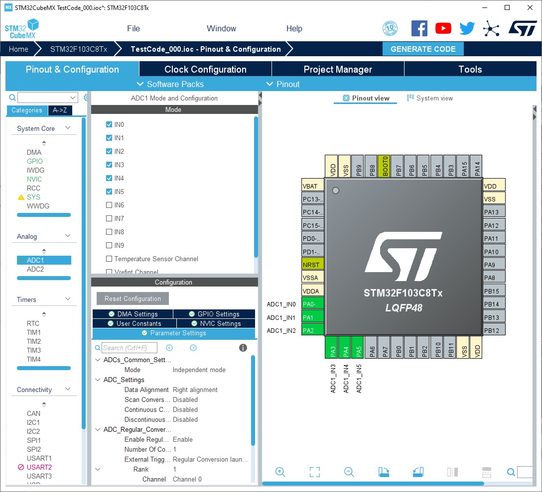
Along with this there is quite an interesting Software development package which is used to setup the barebones structure of the code STM32CubeMX
Very graphical ... similar to FPGA style programming, after this a code project can be generated.
The project code can then be opened with your favorite "C/C++" IDE (even Eclipse after installing the Arm cortex software via "Help" pull down).
You can also plump for the STMicroElectronics STM32Cube IDE
The Toolchain is a bit long winded when you use the official "STM way"... I guess they have to cover all bases.
.............. however there is an easier Toolchain to program the STM32 which will follow in part_00x of this series..... enter the Arduino IDE
STM32F103C8T6 Blue Pill Pin Configuration
|
Category |
Pin Name |
Details |
|
Power |
3.3V, 5V, GND |
|
|
Analog Pins |
PA0 – PA7 PB0 – PB1 |
Pins act as ADCs with 12-bit resolution |
|
Input/output pins |
PA0 – PA15 PB0 – PB15 PC13 – PC15 |
37 General-purpose I/O pins. |
|
Serial |
TX1, RX1 TX2, RX2 TX3, RX3 |
UART with RTS and CTS pins |
|
External interrupts |
PA0 – PA15 PB0 – PB15 PC13 – PC15 |
All digital pins have interrupt capability |
|
PWM |
PA0 – PA3 PA6 – PA10 PB0 - PB1 PB6 – PB9 |
15 PWM pins total |
|
SPI |
MISO0, MOSI0, SCK0, CS0 MISO1, MOSI1, SCK1, CS0 |
2 SPI |
|
Inbuilt LED |
PC13 |
LED to act as a general-purpose GPIO indicator |
|
I2C |
SCL1, SDA1 SCL2, SDA2 |
Inter-Integrated Circuit communication ports |
|
CAN |
CAN0TX, CAN0RX |
CAN bus ports |