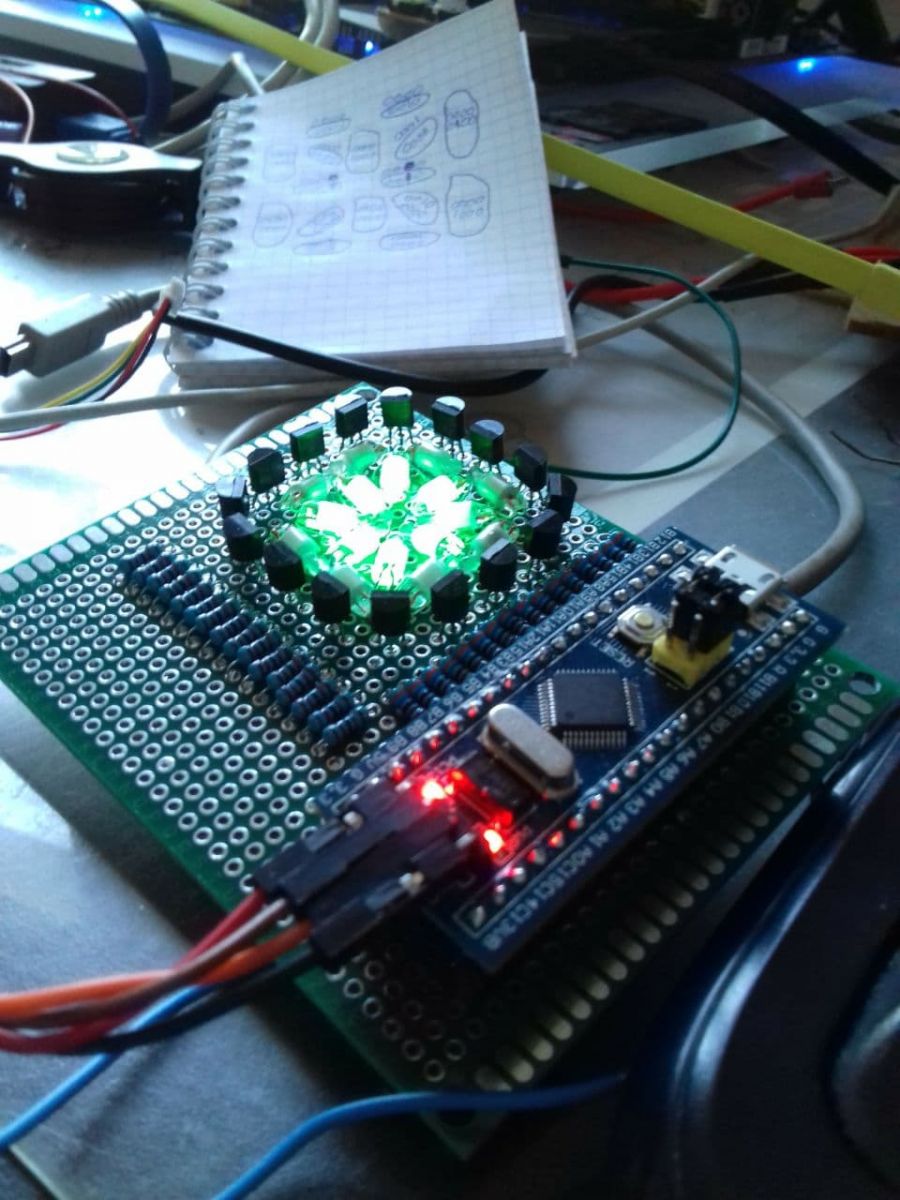
Over the last few months these "Coloured Neon lamp indicators" have been popping up on the matrix, so I could not resit...well who could not resist mixing 3.3volt logic with 170volt.
They come in a variety of colours "Green","Blue" and "Orange" , the glow intensity is good even in daylight.
They all appear to have the same elements inside, however the green and blue have a coating of some kind of phosphor that glows when the base element strikes.
The circuit mpu is an STM32F 103 C8T6 processor (very cost effective).
I have loaded the Chip with a bootloader which is compatible with the Arduino IDE, there are quite a number of variants of this chip and also quite a minefield of bootloaders to boot, so there is no straight-forward formula to match the right chip with the right bootloader .
In most cases the (gd32f1_generic_boot20_pc13.bin) works however In my case I had to use the (naze32_boot20.bin) bootloader. (If both of these fail.....then its a case of testing the other 20 or so bootloader.bin files)
With all the GPIO's this chip has at its disposal gave me the idea to meld it with my bag of Neons.
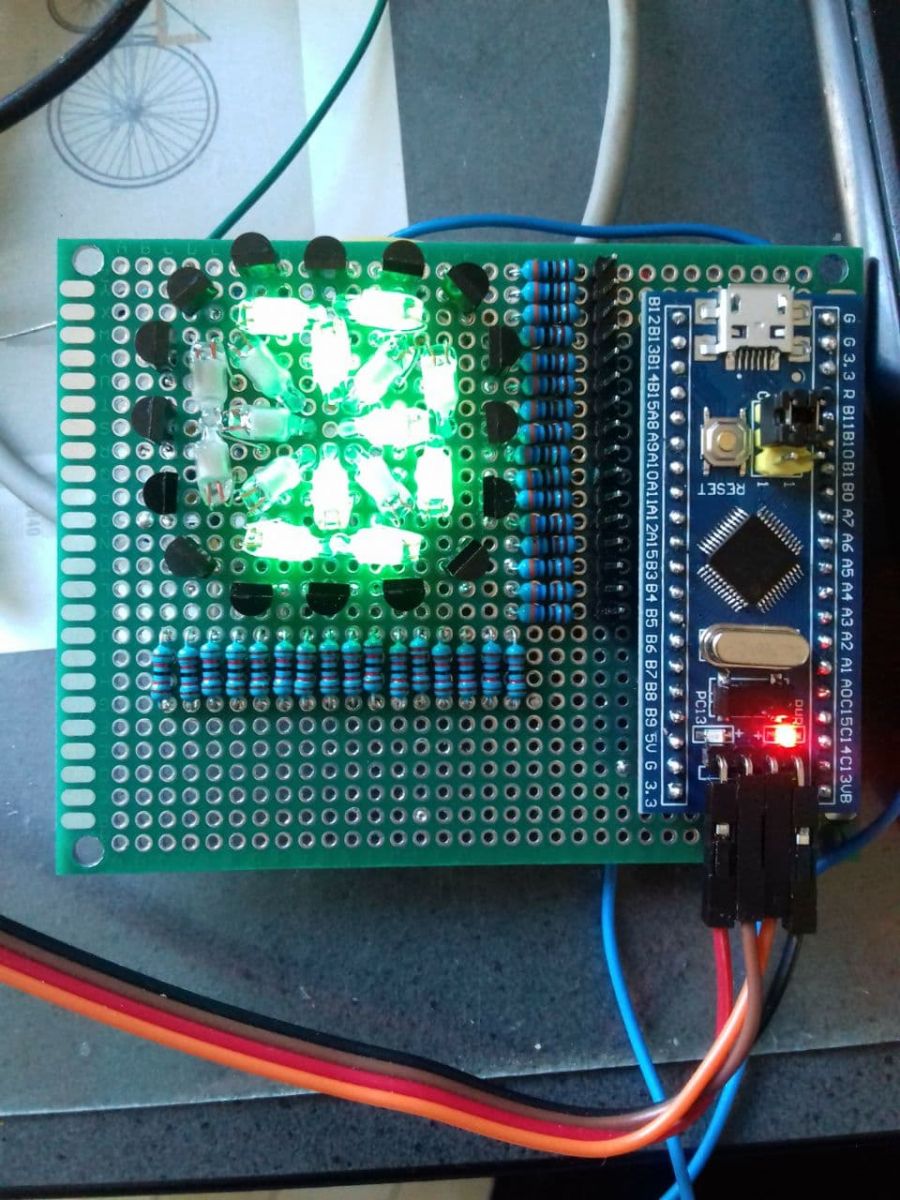
The Neons are arranged in the classic AlphaNumeric style, which means that the whole alphabet
and number/symbol characters can be displayed. (Inc some cool icons).
The 3.3volt Output logic feeds a 3.6 ohm resistor connected to the base of a MPS A4Z transistor (these are High voltage NPN transitors capable of switching 300V @500ma).
In this case the transistor switches 170V supply across the Neon+inline resistor (which takes <1ma to operate).
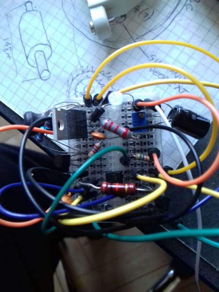
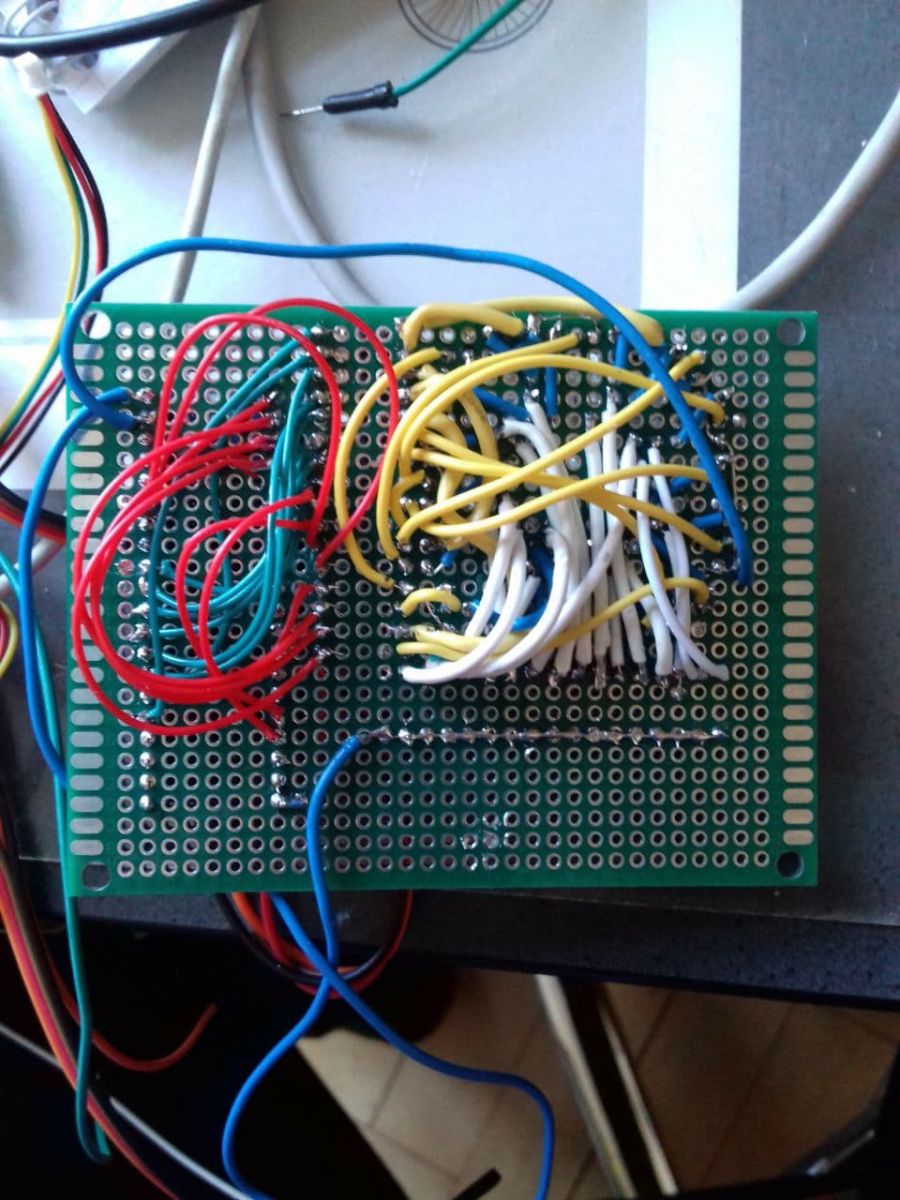
The reverse is a rabbit warren of wires, an artform in its self...
Still to be put onto the motherboard is the 170Volt inductive-mosfet generator,
with at its heart is an NE555 timer in astable modus running at 30kHz.
This might be upgraded by using the STM32's interrupt system, however at the momo i have not the right "life experience" of the chip to apply yet (we see).