Hi guys! :)
I have a project that uses arduino and pan/tilt servos to track a desired color. With the use of a camera and myrobotlab, this project slowly come to life. I and with the help of GroG, are working on it to make it possible. However, it's not yet done and the project is still under progress. Here's some of the highlights of the project. Comments and Suggestions will be greatly appreciated :)
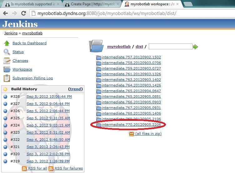
First, you need to download MRL:
-you can download MRL at this link. Be sure to pick the latest build ( at this time of writing, the latest is ver.770) Here's the link: http://myrobotlab.dyndns.org:8080/job/myrobotlab/ws/myrobotlab/dist/
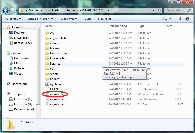
Next is you have to extract and open the folder and open myrobotlab.bat file:
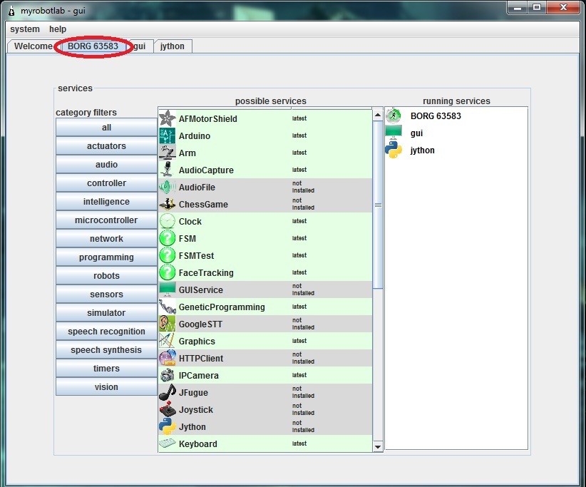
After a while it should run like this:
Notice the BORG tab selected :)
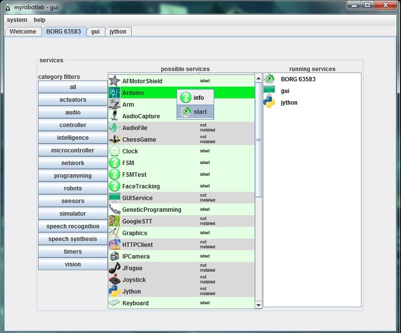
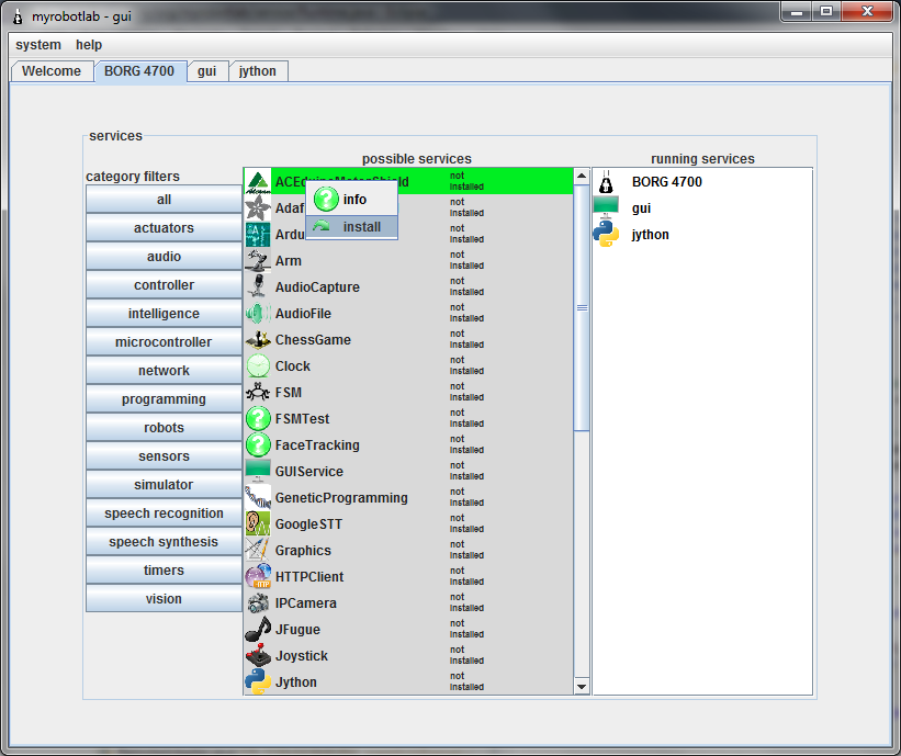
Next is you should download the arduino service. Just right click the arduino service and click install. The same procedure applies to the OpenCV service
NOTE: Some anti-virus programs don't permit downloading the services. For me, I turned of my firewall and it worked.
Here's a pic (disregard the start under the info. It should be install because I already downloaded the service)
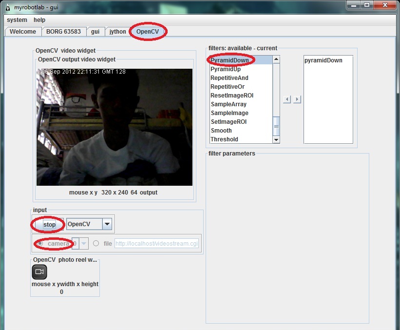
After downloading the Arduino and OpenCV service, Run OpenCV service by right clicking and choosing start. Then, name your service. Here I called it OpenCV. Click the OpenCV tab and scroll down the filters and select the PyramidDown filter to avoid the video booming up in your screen XD. and select the camera button then press capture. Normally the stop button is capture. :
Next is select the InRange filter to select the color you want to be tracked. Click the Inrange filter. Play with the values until the desired color will become white.
Pic:

Color tracking is a bit sensitive. Sometimes you should be consistent with the color ( due to poor lighting and etc. that affects the color consistency) so you'll have to update those values sometimes to get an accurate output.
Now, if you are all set, Remember the values in InRange filter. Like this from the picture above:
Parameters Min Max
HUE 3 33
SATURATION 87 256
VALUE 151 256
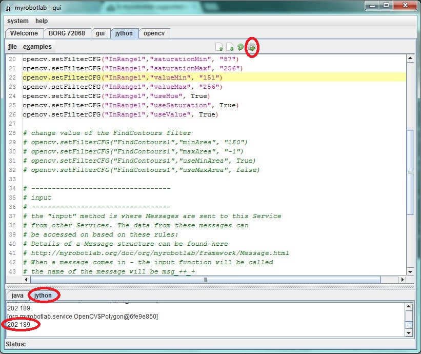
If you are done taking down the values select the jython tab and copy these codes. You NEED to replace the values in "change values of the InRange filter with your own values that you took down down a while ago.
Now if you are done copying. Hit execute button( the button with a gear :D) . Notice in the pic below the jython console is printing x,y coordinates that later will be sent to arduino.
Now, start arduino service and follow these steps:
1- click tools and choose board then select the arduino model you have
2- click again tools and choose Serial Device then select the proper COM port the arduino uses(at this time your arduino should be connected in your computer)
3- click the compile (check) button. Wait for it to finish compiling (when you see a "done" in the console)
4- click the upload button and again wait for it to finish
5- click the connect button. Wait for the "good times"
Test the connection by clicking the pins tab and selecting some analog pins to active. Put some wires or sensors (potentiometers, etc.) to the analog pins. Then, select oscope tab to view some values sent to the myrobotlab.
Stay tuned :)
Great Project Michael !
Try this script for the Arduino.
You should see an Arduino service start up, wait a bit - for some reason initialization of the com port takes a while on windows 7 64 bit - the delay is from the native dlls in the RXTXCom module
After about 8 or 10 seconds - flip over to the oscope and see if a analog trace on pin A0 is running...
from time import sleep from org.myrobotlab.service import Arduino arduino = runtime.createAndStart('arduino','Arduino') # set and open the serial device # arduino.setSerialDevice('/dev/ttyUSB0', 57600, 8, 1, 0) arduino.setSerialDevice('COM6', 57600, 8, 1, 0) sleep(4) arduino.pinMode(14, Arduino.INPUT) # arduino.digitalReadPollingStop(7) arduino.analogReadPollingStart(14) # A0The previous script takes
The previous script takes about 20 seconds to start up on my system - this is all because of the way RXTXComm behaves on windows 7...
I've noticed Arduino IDE takes the same amount of time to start.
This happens:
That looks like - a lot of
That looks like - a lot of nothing ...
hmmm... try updating
help->about->I feel lucky
restart
try again - wait on the jython console for 20 seconds - if it starts up correctly you should see alot of debug logging scroll by in the java console
if it still "no-worky"
click the help->about->GroG, it no worky button
You'll be the first to test my new auto-send log & debug report system !
I'll try it again :)
I'll try it again :)
Got the log file, thanks
Got the log file, thanks ...
it "looks" like the board is sending info back .. don't know why the oscope is not updating...
I'll have to look at this some more...
Okay :) BTW, congratulations!
Okay :)
BTW, congratulations! your "no-worky" button worked. Cheers to that :D
Um ..
"Sort of work", I got your log file but it was 2 Megs of pin data coming from the Arduino :P ... not much else,, which I'm a little suprised about ... I thought it would be "everything"
It looks like stuff is working, its just not updating the display... try waiting on the jython page until, you begin to see data scroll by in the Java console.. if you've already done this, try it - but before you execute the script - go to the menu
System -> Logging -> Level -> INFO
This should clear out all the publishPin log statements - make note - you shouldn't see anything scrolling now...
There's no analog trace when
There's no analog trace when I tried it again. (with the system-logging-level-info...) ,
But, I noticed a different value from the recent picture that I posted. The differences are:
the mean, min. the min from the recent picture shows 0.
Here's the pic:
HA ! It is working, you just
HA !
It is working, you just have it off the scale !!!
You've got that pin tied to 5 Volts ;D
Untie it from 5 volts and just stick a wire in it - the wire gives it plenty of deviation, so you can see the trace... but @ 5 Volts its off the screen !
I'm looking into making the
I'm looking into making the screen size as big as 1024 now ... thanks for finding that bug ;)
Figured it out!
The values are off the chart because the servo shield provides 2 pushbuttons connected to pins A1 and A0.
Do we have to really use the script? cause the pushbutton is permanent. Thus, A0 will just give us "off-the-charts" value XD
More available options are good
We can do it with or without script, however, your MRL will become more and more complex - because your going to add more devices and more functionality.
To initialize all that, its much more convienent use a script, some things like message routing is more challenging to do graphically.
I'm not suggesting we use our current Arduino script, obviously it doesn't currently work for your system...
No worries... I was just trying to make sure your Arduino will be responsive to "a script"...
Alright,
So do you have any free analog pins ? - Just restart and change the pin value in the script to a free pin - then you can use it as a valid sensor...
Also,
to move on... what does your robot do now? Can you attach a current PDE script your using for it? Does it drive around in a circle, bump into walls and try a different route?
Okay. I've tried it again but
Okay. I've tried it again but no luck. I've hit No Worky now :)
Finally!
Finally it worked :)
Great - So let's get
Great - So let's get organized now...
At the bottom of your post you currently have a working OpenCV script, and now we have a working Arduino script, we will continue to build scripts around the Services independently - until we like the results - So add the Arduino under the OpenCV
e.g.
# OpenCV Script
# Purpose - initializing the OpenCV service and start color filtering & publishing of coordinates
# of the contours found
.....
# Arduino script
.... etc
# PID script
etc...
After that - the next step is getting them all to talk to one another ..
So it should look like this?(
So it should look like this?( disregard th "/". Just to avoid confusion)
# /////////////////////////////////////////// OPENCV///////////////////////////////////////////////////////////
from java.lang import String
from time import sleep from org.myrobotlab.service import Arduino arduino = runtime.createAndStart('arduino','Arduino') # set and open the serial device # arduino.setSerialDevice('/dev/ttyUSB0', 57600, 8, 1, 0) arduino.setSerialDevice('COM7', 57600, 8, 1, 0) sleep(4) arduino.pinMode(16, Arduino.INPUT) # arduino.digitalReadPollingStop(7) arduino.analogReadPollingStart(16) # A2Right, I put #'s in front of
Right, I put #'s in front of the dividers - because these are comments in Python...
So to get off where you left, you just have to copy/paste the whole script in..
Still working on the Shield... I'll keep you posted..
Take your time :)
Take your time :)
Servo Shield question.. Can
Servo Shield question..
Can you test the shield without MRL ?
E.g. can you drop the shield library in and test moving the pan/tilt kit ?
Can you post your Arduino Shield code you used to test the pan/tilt kit? I suspect it would be very similar to the example from the library...
I want to make sure we have a "controlled" test... such that we know the library, arduino, shield & servos work in at least one context ... then we can try them & the new service in MRL
Here's a code moving the
Here's a code moving the pan/tilt servos using 2 potentiometers:
////////////////start of arduino code//////////////
#include <ServoControl.h>
Excellent, thank you ... that
Excellent, thank you ... that is very helpful - thanks for the video too
If a "picture says a 1000 words" a video says 30K words per seconds ;)
It seems a bit jittery and a bit flakey in response in the video ? Do the servo's brown-out (stop working when you move them too fast) ? Some of that could be that they might be underpowered.
What is your feelings regarding the control of the servos? What things have you noticed?
Servos are not the problem :)
Servos are not the problem :) It's jittery because of the potentiometers I used. My wirings are not stable. Thus, giving an unstable values. :)
BTW, how's the progress? are we near completion? I'm so excited cause when we accomplished this project, there's infinite of possiblities we can make in the future.
After accomplishing this, I am thinking of a robot arm that tracks a color so we can apply this project and grab that object when the desired distance between the object is met. Is this possible? :))
Ok, the more unstable the
Ok, the more unstable the lower levels are (hardware & connection) - the more difficult it is to track (just so you know), it's always best to attempt to filter out noise at its source, rather than make software that compensates...
Progress is good, in that I know how I want to implement this, additionally, it will be helpful that you have a controlled way of moving the servos - so we can compare..
Still have a bit to do... and I have other responsibilities too :)
but I'm trying to get done..
Sure its all possible,
If I could get done with this I could start working on the 3D Point Cloud SLAM with a kinect :D http://myrobotlab.org/content/openni-mrl which would give a robot a 3D map to navigate through
I posted the MasterAndBrains
I posted the GlueAndBrains Python script and MRLComm2 script in your post.
I suggest try the following :
If something flakey happens I would recommend at some point - downloading the latest (complete package) as your post illustrates, should be intermediate.777.20120908.2154 or later
I can't test this obviously since I don't have the hardware.... :)
Good Luck...
Umm. There's a problem :(
I've uploaded the arduino code, updated the MRL, ran the jython script but there's no movement at all.
the opencv service seems working correctly because it only tracks one color. Here's a screenshot:
And, I just have a question:
The Arduino did not come up -
The Arduino did not come up - not sure why....
The details of which servo are not in the Arduino code, but are now in the Python...
Specifically, it's in the Python shield code...
Looking at your log file now - can you try just the Arduino's Python, I would expect to see a tab after you run it...
I've sent you another logfile
I've sent you another logfile :))
I tried and ran it again. The arduino tab opened. Unfortunately, it does not work again :(
Here's a pic:
Hmmm.. don't see any ERRORs
Hmmm.. don't see any ERRORs in that one...
In the future, don't put in the OpenCV stuff ... let's isolate it to the Arduino & Shield only...
I think that's the best step
I think that's the best step for now since the OpenCV is running properly. In isolating the arduino and shield, we can specifically determine the problem.
BTW, I don't know if I asked this question already. My question is, can we directly send the x,y values to the arduino via serial and there we will just map the values? But it's good to have a specific service for us to control the servos in the servo shield.
When you start the arduino
When you start the arduino and shield only.. does the analog trace come up on the oscope as before?
Yes it does :) Here's a pic
Yes it does :)
Here's a pic for confirmation:
That's good, There are no
That's good,
There are no ERRORs in the log - (thanks for the new one)...
I did noticed .. shield.start() was getting twice, so I removed the second call, and removed a servo just to reduce complexity.
So the python script now is
So the python script now is edited and I should try it again isn't it? :))
Yes, Make sure you don't
Yes,
Make sure you don't have any updates with the "bleeding edge button"
Then give it a try with the new Jython script (leave OpenCV out of again)
what do you mean about :
what do you mean about : leave OpenCV out of again?
I tried the new script but it isn't working. The thing is, the servos are jittering but not as close to the position of the color.
BTW, I do have a realization about how the pan/tilt are tracking color. Isn't that, for example:
The color have the coordinates 160,150. Then, the servos are going to position based on the x,y coordinates mapped to 500-2400 uS. At the time that the color is set on the center of the camera based on the coordinates, say for example, it's coordinates will be now 90,90 (but the real position of the color is at 160,150) So, the servos will follow the 90,90 coordinates and the color will now be out of line of sight.
Is this problem is resolved by using PID?
Sorry, I've been studying PID since yesterday :))
For me, the best step for now is to verify Aceduino Shield service runs successfully. In order to that, can we try to use the scrollbar/trackbar in the service to position the desired servo?
"what do you mean about :
"what do you mean about : leave OpenCV out of it again?" <- I mean when you run the Python script just use from the # //////////////////////////////////////////////////////////////// ARDUINO ///////////////////////////////////////////////////////////
down.... don't copy in the OpenCV part
"I tried the new script but it isn't working. The thing is, the servos are jittering but not as close to the position of the color."
Really? This might be a case of it working when you think it's not :P - At this point I don't expect it to follow the color target. I want to validate the shield is working with the Arduino and Shield service.
This is the key part of the code:
This key part of the code
This key part of the code somehow actually works!:
Great news ! Can you give me
Great news !
Can you give me more info ?
Can you give me the steps involved now in making this work ?
If you shut it down, can you restart & get it to behave correctly again ? consistently ?
Last night it worked properly
Last night it worked properly as the key part of the code states. But when I tried it again today, servo port 7 (as stated in the code) don't move :(
Servo port 7 is to be used right? I'll try it again today and post some results later. I will try to work it again.
I will send you a logfile now to verify the script's working :)
These should be your steps
These should be your steps :
Is this key part of the
Is this key part of the script runs for a loop? cause I noticed (hopefully) some movements like it goes for 90 degrees then about 150 degress then nothing.
this key part I'm referring to:
It sounds like its working
It sounds like its working !
It's not a loop !
Just keep adding stuff .... I just wanted confirmation that it has control of the servo.
To put it in a for loop do the following,
this should move the servo from position 0 to 90 to 180 then back to 0 for 30 times.
Careful of the indentation.. Python is very picky when it comes to the code lining up.
Do I have to add it in the
Do I have to add it in the main aceduino shield code?
I have made getting to our
I have made getting to our position in color tracking much easier.
You will need to download the full zip (do not just update throught the bleeding edge button). This is necessary because contents of the repository have changed.
Once you have downloaded it and unzipped it - right-click -> install AceduinoMotorShield
This will download all the necessary components for the ACEduino motor shield to work (I hope :) ....
Including, downloading the Aceduino motor shield library, and putting it in the correct place.
Pretty cool, huh ?
Now in the jython's service tab is the script we are working on .
You can remove the OpenCV part - to make it simpler.
When you execute it should start an Arduino & ACEduinoMotorShield.
Additionally, the Arduino service now comes with examples -
a MRLComm example which is basic arduino communication without any shield libraries
and now ACEduinoMotorShield (soon to have AdafruitMotorShield too)
Can I directly upload the
Can I directly upload the AceuinoMotorShield.ino now in the arduino service?:)
You "should" be able too...
You "should" be able too... It's still a little flakey, but I'm refactoring as quickly as I can :)
It's no work GroG. However,
It's no work GroG. However, I've sent you the logfile now :)
I think we should just resort to using the Original Servo lib. For now, I will not use the servoshield.
Fortunately, it has 2 digital sensor pins(2,3) that can be used as ports for pan/tilt kit (perfect!). 1 port have I/O (can be used as input for the servo) GND, and Power supply.
I'm sorry for the time you wasted in adapting the aceduino motor shield to MRL. I'm still hoping that we can accomplish this project :))
Not time wasted, just
Not time wasted,
just getting closer to borg'ing in another piece of hardware ;) !
Anyway, if your going to use the regular Servo library then you need to upload - the original MRLComm.ino
It's the Arduino ino which comes loaded by default in the Arduino editor - please try the following and tell me the results :
Good luck
GroG it's working now!
GroG it's working now! :)
However, it's not running in a loop. The servos just run as what the script's written.
Let's try now the full script :)
Please change the servo script cause it's still in the loop :)